Circuit diagram 2007/02/18 ![]()
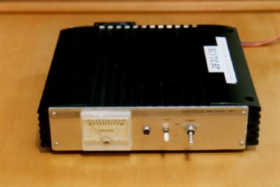
Place seen from the front
This was used till February,1999
year. For 6m It is its original work linear amplifier. A stone
called MRF454 is used by the push pull. Main walkie-talkie of
those days 10W of IC-726 are inputted. Output of 100W It uses.
It stored in the case of
amplifier ゜ for car audios, and the parenthesis was improved
rather.
Since the aluminum panel of an order side did not have a tool, it was cut and made from saw for metal cutting. It is HI which cannot show a rise photograph since it has turned at a few if it sees well.
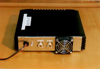
It just saw from back
Although it was 13.8V as a standard, the power supply raised voltage for a while, and since it seemed that the quality of an electric wave of the way of feeling was good, it was always driving it by about 14.5V generally. A change relay will be turned on [ it ] if the right of a power supply cable drops on a ground with a SEND terminal at the time of transmission.
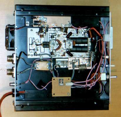
Inside seen from the top
24V fan It turns by 13.8V, and about quiet cooling, since the case itself is fairly large, if midsummer is also touched, it will become only realization and a grade (about [ MAX50C degree ) of somewhat hot case. There lid was shortened purposely, the crevice was made in the front panel lower part, and the air for cooling is taken in from there. Since a large suction mouth is made, it is playing a role also in wind end sound reduction.
Although the change of transmission and reception is using the power relay LY type of cheap OMRON Corp., the signal course inside a relay was straight converted by Resources JF3DRI Mr. Nishimura's advice (a one turn will be carried out, when a high frequency signal is transmitted to a lead, if normal), and further, the outside case top shielded with the copper plate, and has lowered impedance. however, loss of a received signal can check a little -- it seems that it is a grade However, it is not the grade which poses a problem.
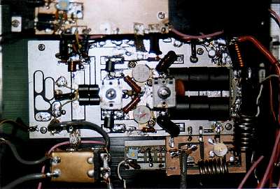
They are the main circuit partial details.
A substrate is a substrate of a HF linear amplifier kit called PE-L1 which the place called special electrical machinery of old days was taking out. It says [ reconstruction ] to the object for 50MHz from the object for HF. NFB was removed and the input-and-output transformer was manufactured. Although the output side is using six 6 B-2 material, its generation of heat is [ at least four pieces ] the same few. In 801x4 FB(s), an input side does not have generation of heat, either and was made small. Some capacity also exchanged for the thing of big capacity (600p). a gain not going up well in the beginning, but oscillating not being stabilized various worrying in the end NFB light hanging things stable operation it came to carry out Transceiver
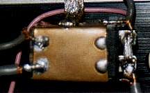 Transceiver change
relay details
SPL TNX JF3DRI
Bibliography Linear amplifier stylebook CQ, publishing company