Now let's see how a circle appears in the Hyperbolic Non-Euclidean World by using a hemisphere model.
We are not using the hemisphere as a model, but rather as a tool. We make a circle on the surface of hemisphere, and project it onto Poincare's disk or Klein's disk. A ball is used instead of a hemisphere for projection to
Poincare's disk. The radius of the circle we are using here is finite. The circumference of a (hyperbolic) circle with a finite radius does not touch infinity (disk edge).
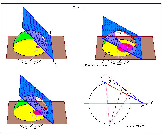
Look at Fig. 1 above.
The yellow disk is Poincare's disk on the brown equatorial plane. The blue plane is hinged to straight line ab on the equatorial plane and slices through the hemisphere (the upper half of sphere). Let us call the blue plane Slicer for convenience. The radius of sphere is infinity.
Slicer slices the hemisphere and makes a circular hole (cut end) on it. The circle is projected to the south pole S of the sphere through the equatorial plane and forms the red circle in the yellow disk.
The side view at the right bottom is parallel to the hinge axis ab on equatorial plain BB', which is shown in a horizontal position. Point t is the point at which Slicer first touches the surface of sphere. The hyperbolic center of the red circle is point C, which is the intersection (piercing point) of the black dotted projection line St and equatorial plane BB'. The projection line St will not change if we lean Slicer while hinge axis ab is fixed on equatorial plain BB'.
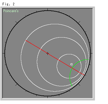
Look at Fig. 2.
This is a bird's-eye view of what happens when we lean the Slicer without moving hinge axis ab. The yellow disk in Fig. 1 is drawn in black, and the red circle in white. We get concentric circles because they have a cmmon center C that doesn't move. We leaned Slicer so that the radii of circles are 0.5, 1, 1.5 in sequence. The red straight line and green (hyperbolic) straight line are a pair of diameters that are perpendicular to each other. We have chosen the red diameter passing through the origin for easy observation.
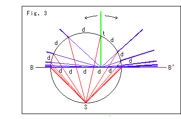
Look at Fig. 3.
Now, let's insert hinge axis ab into the sphere. The green line is the upright Slicer. The slopes of Slicer are at regular intervals (distance 0.5, 1, 1.5, ...) on the sphere from point t.
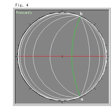
Fig. 4 is a bird's-eye view of Fig. 3. The curved lines correspond to the cut ends on the sphere. The green line corresponds to the green upright Slicer, and the white curved lines correspond to the leaning blue Slicer. The intersections of these curved lines and the red, horizontal straight line correspond to the intersections of the red projected lines and base line BB'. White lines are spaced from the green straight line by the same interval as above (0.5, 1, 1.5, ...). That is, they are equidistant lines.
When we understand that the concentric circles in Fig. 2 are equidistant lines with respect to the center C, it is no wonder that we got equidistant lines in Fig. 4.
Now, you may ask, if hinge axis ab comes into contact with the hemisphere, what will happen? We'll see the answer to this question later.
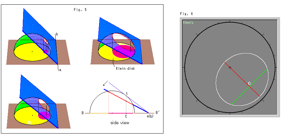
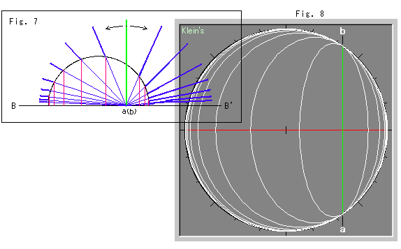
Fig. 5 to Fig. 8 below, are provided so that you can compare them with the Klein's disk. You can scroll them up and see.
