As we saw before, a disk model is a disk that is compressed at every point in all directions. Here we think to the contrary. If we expand ever point on the disk as shown right. But if we do so, it will be a saddle shaped. (Such a waved plane is not an actual hyperbolic plane.) We try to maintain a flat disk to the utmost. Therefore it is not accurate as a hyperbolic plana. But it is useful to get an idea.
In the latter half we will see how hyperbolic disk is compressed without dis-compressing.
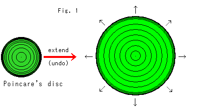
Look at Fig. 1.
How much is Poincare disk compressed? It is being enlarged to all points of the compass. Gaps of concentric circles in the central area are even. It is OK in the radius direction but length of circumference of the concentric circles is incorrect.
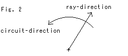
See Fig. 2.
Here, we stretch the model in the ray-direction and circuit-direction. In this case, when we say "circuit-direction", it means that it is going along the circumference. It is not referring to a tangent to the circle.
The ratio of circumference to diameter in the Hyperbolic Non-Euclidean World
is not constant ![]() . The circumference is
. The circumference is
Let us change this formula this way:

We call the fraction in parentheses hyperbolic-pi, and denote it by ![]() . That is
. That is
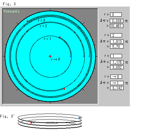
Look at Fig. 3.
Each circumference of concentric circle curls up when we stretch the disk in the circuit-direction. Spirals actually have no thickness even when curled, but these have been drawn for easy observation. Hyperbolic-pi ![]() increases very rapidly when the hyperbolic radius r gets bigger. When the hyperbolic radius r gets close to zero, hyperbolic-pi
increases very rapidly when the hyperbolic radius r gets bigger. When the hyperbolic radius r gets close to zero, hyperbolic-pi ![]() becomes almost equal to ordinary
becomes almost equal to ordinary ![]() .
.
Fig. 3' represents one of the spirals in the shape of a coil. We may imagine that we are going under the disk surface, although it actually has no layers. (The disk will be wavy if you absolutely insist that the disk is a single face.)
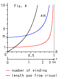
Look at Fig. 4.
R is the visual distance from the origin on the disk model (radius of concentric circle). Hyperbolic radius r corresponds to visual radius R..
The blue curve indicates that hyperbolic-pi ![]() changes with respect to visual distance R.
changes with respect to visual distance R.
The red curve shows the number of windings sinh r / r . For example, it is 3.339 when r = 3 (R = 0.905). This value is the same as shown at the top right of Fig. 3.
The black curve is the difference between the hyperbolic circumference 2![]() sinh r and the visual circumference 2
sinh r and the visual circumference 2![]() R.
R.
In the Hyperbolic Non-Euclidean World, when radii are 1m, 2m and 3m, circumferences are 7.38m, 22.8m and 62.9m respectively. That does not matter much. But if a radius is 100m, the circumference will become the astronomical figure of l8.4x![]() m. Compare it with one light year, which is 9.4 x
m. Compare it with one light year, which is 9.4 x![]() m. Imagine how large this would be!
m. Imagine how large this would be!
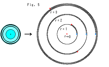
Look at Fig. 5.
We will draw the disk smaller and stretch spirals in the ray-direction, leaving the disk so that spirals have actual radii to our own eyes. Except for the spirals, all other area is meaningless. The spiral with a radius of 1 is drawn in the same size as that of the disk edge. This is because the radius of the disk is also 1.
Fig. 6 and Fig. 7 below show the relation between visual distance R from the origin and its real hyperbolic distance r.

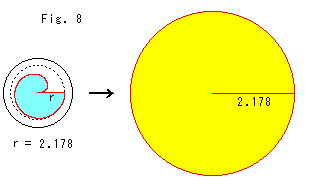
If we try to make a plane with a circumference of spirals as in Fig. 5, the plane will take on a screw shape and will have layers. So we cut out the disk model in the sky blue shape as shown in Fig. 8, and we will stretch it in the circuit-direction and ray-direction. Then we get the yellow disk. On this yellow disk, only distances in the circuit-direction or ray-direction are the real hyperbolic distances in the sky blue disk model. The angle on the yellow disk does not correspond to the sky blue one, because the yellow disk is not a real hyperbolic plane.
As for the angle, we do not need to expand it because the angle in a Poincare's model is just as we see it.

Look at Fig. 9 above.
It is based on the same idea as Fig. 8.
[1]: It is a sector aOb on Poincare disk. ![]() is our optic angle at the origin O. It meets with hyperbolic angle as it is. We cut the sky blue sector out.
is our optic angle at the origin O. It meets with hyperbolic angle as it is. We cut the sky blue sector out.
[2]: And we stretch it in the circuit-direction and ray-direction. Then we get the yellow leaf. The leaf is jutted out from the optic angle ![]() because red curves are expanded actual hyperbolic length. It would be fine if light beam curves like black or green curved line and comes into our eys. But it is hopeless. However, on hyperbolic plane we can see such big length as red curves within the optic angle
because red curves are expanded actual hyperbolic length. It would be fine if light beam curves like black or green curved line and comes into our eys. But it is hopeless. However, on hyperbolic plane we can see such big length as red curves within the optic angle ![]() . No beam of light curves.
. No beam of light curves.
[3]: We compress the leaf from both sides as shown arrows so that the entire leaf stays within the optic angle ![]() . We can not keep the leaf as a flat plane but we have to make gathers.
. We can not keep the leaf as a flat plane but we have to make gathers.
[4]: We turned and slant [3] a little. Now we can see the leaf with big wave.
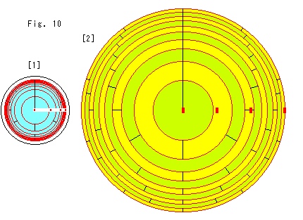
Look at Fig. 10.
This time we do not make a cutout, and we extend the disk model in the circuit-direction only.
[1]: The maximum radius of red concentric circles is 3 in hyperbolic distance. Why we set the size of the red concentric circles as 3 is due to the fact that we can not draw it when we are going to get actual hyperbolic length. The four red marks in the horizontal row show the distance from the origin at regular intervals of one hyperbolic distance.
The expanded disk is colored alternately between the red concentric circles for easy observation. Let us temporarily call them Belts. The red concentric circles consist of circles that pass where real hyperbolic distance in the circuit-direction becomes 2, 3, 4,![]() times the visual distance. The outer edge of every Belt is longer than the inner edge by (when extended in the circuit-direction) one hyperbolic circumference in length. The black partitions on the Belts show this. A sector (between adjacent partitions) becomes one round length measured on the inner edge when it is extended in the circuit-direction to the actual hyperbolic distance.
times the visual distance. The outer edge of every Belt is longer than the inner edge by (when extended in the circuit-direction) one hyperbolic circumference in length. The black partitions on the Belts show this. A sector (between adjacent partitions) becomes one round length measured on the inner edge when it is extended in the circuit-direction to the actual hyperbolic distance.
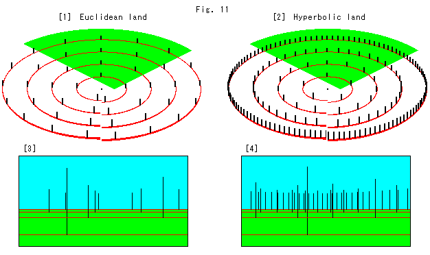
Look at Fig. 11 above.
[1] is a flat ground where Euclidean geometry works. There are concentric circles with the center at the origin. Pillars stand at regular intervals of distance measured from the other side along a circle. All the width of intervals on each circle is constant. Each circle cut at our side is due to the fact that we can not make continuous regular intervals.
[2] is a flat ground in the Hyperbolic Non-Euclidean World, where hyperbolic geometry rules. However, the flat ground is compressed in the circuit-direction though length in the ray-direction is perfectly hyperbolic.
Therefore, the bigger a circle becomes the more pillars are crowded in, even though the row of pillars is exactly the same as that of [1]. To avoid the crowd we have to bend the flat ground in the shape of a saddle, or use a
compressed ruler. This ruler is an arc that fits a circumference and measure in a scale that shrinks at a distance from the origin.
[3] is a photo picture taken from neighboring the origin. The green sector is the field of camera vision.
[4] is a photo picture taken in the same manner as [3].
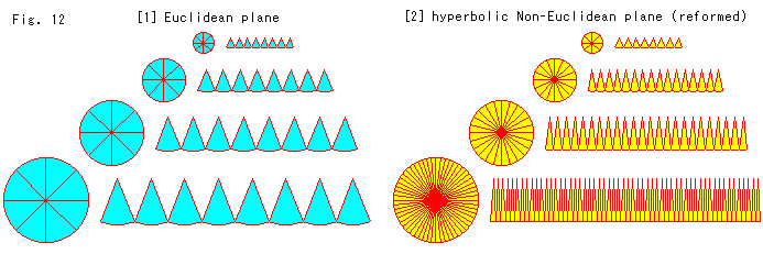
Look at Fig. 12 above.
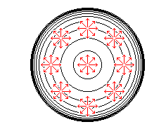
[1]: We cut circles in secters and lay them on a line. The radii of circles are 1, 2, 3 and 4 from top to bottom.
[2]: We reform the hyperbolic Non-Euclidean plane so that we are able to treat it like Euklidean plane. In order to avoid the saddle shape we compress around a required point in circuit-direction only. The yellow figures are drawn on such plane. We draw circles that are equivalent in size to those of [1]. Let us consider the compression in circuit-direction in every circle to be homogenized. The shape of cutouts is an ordinary sector, not like a leaf in Fig. 9. However, the number of yellow sectors we get from a circle increases rapidly by sinh (hyperbolic sine) r as the raidius r gets bigger because every circle is compressed in circuit-direction. In case of above figure, the number of yellow sectors becomes approximately 4, 8, 12, 17... as radius r gets 2, 3, 4... although it appears to have almost no change at r = 1.
We just made a flat surface by force, and saw just how much a real Hyperbolic Non-Euclidean World (plane) is compressed onto a Poincare's disk model.
If we want to get an accurate mental grasp of the compression, it is necessary to use measurements that are microscopic in their viewpoint.
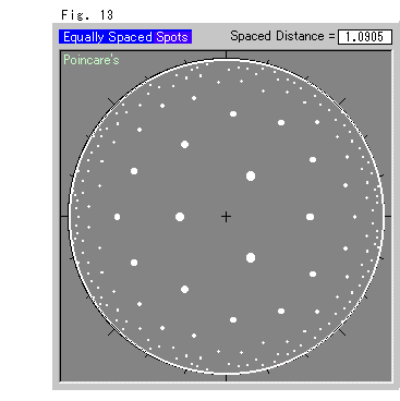
Now we are going to see Poincare's disk model itself without stretching, and see how it is compressed.
Fig. 13 shows spots scattered at a regular interval in the model. All the spots are the same size. The farther we go from the origin, the smaller the spots and intervals become to our eyes.
(There is no other pattern where the spots are equally spaced. (cf. Ch. 12))
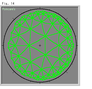
Fig. 14 shows (hyperbolic) straight lines drawn between consecutive pairs of spots in Fig. 13. Each mesh is a hyperbolic regular triangles. The interior angle is ![]() /7, and seven hyperbolic regular triangles gather at a point. Naturally it is impossible in the Euclidean World.
/7, and seven hyperbolic regular triangles gather at a point. Naturally it is impossible in the Euclidean World.
Fig. 15 shows dots that are dispersed randomly, but the number of them in every certain hyperbolic territory is fixed. Let us call such dispersion hyperbolic spray.
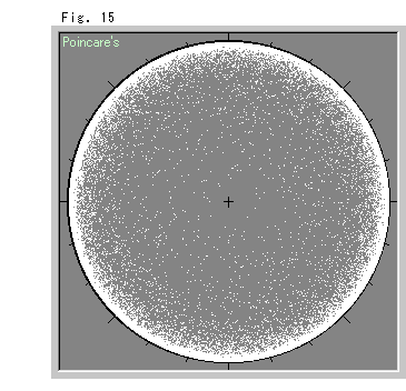
It would be good if we could homogenize the spray to see a real surface in the Hyperbolic Non-Euclidean World. However, we have seen that it is impossible on a flat surface.
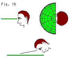
Fig. 16 is just for fun. Hold Poincare's or Klein's disk and see it as shown in the figure. You can find a scene enlarged in distance, even infinity! Try.