
Ch. 44 Projective Geometry (3) 
We will make Klein's disk model from projective plane. The following is not the same as the process of his discovery, but we follow his way of thinking.
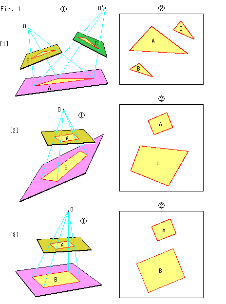 Look at Fig. 1.
[1] shows triangle A on the pink plane below and its projected triangles B on the yellow plane and C on the green plane. Triangles A and B are projectively identical seeing from projective center O. Triangles A anc C are also projectively identical seeing from projective center O'. Triangles B and C are also projectively identical, but we cannot find a single projective center for both of them. A movement with only one projective center is called perspective transformation. To transfer triangle B to triangle C, we have to move triangle B to trangle A on the pink plane (B changes as A) and then project it to triangle C on the green plane.
[2] shows a single plane on which three triangles A, B and C are placed all together. What is called a projective transformation is applied to figures on a single plane (projective plane) like this. It includes the direct movement from triangle B to triangle C. Transformation of a figure means how to move it. A projective transformation transforms a point to a point, a straight line to a straight line, and a quadratic curve to a quadratic curve.
The projective transformation is a transformation that moves not only a point to another location but also changes angle and length. That is to say, there is no ordinary metric on a projective plane. Projective geometry does not care angles, distances and congruence. But we will be in trouble if angles or distances change when we move a figure. Therefore we set conditions on the projective transformation so that distance and angle can be defined. It is called metrization.
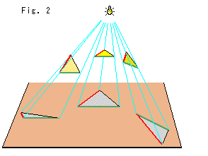
Look at Fig. 2.
When we turn a triangle under a light bulb, its shadow changes variedly though the triangle itself is unchanged. The shadow forms an acute angled triangle or an obtuse angled triangle, or turn over them, or a segment in a case. It is convenient if we can get the original angles and length of sides by measuring the shadow. Suppose we can do so, let us say that all shadow triangles are congruent. Triangles in Fig. 1 are also congruent in the same meaning. However, it is better to say "correspondence" rather than congruent until we can get metrization. You know, a projective plane has no concept of length and angle.
 Now we draw a unit circle (circle with radius 1) on a projective plane as shown in Fig. 3. We are going to make it into a disk model.
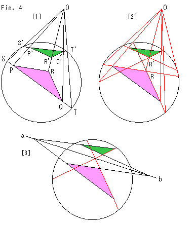
Look at Fig. 4.
[1] is a construction to move a triangle with a projective center set outside of the circle. We move the pink triangle PQR to the green triagle P'Q'R'. Vertices P', Q' and R' correspond to vertices P, Q and R respectively. To move triangle PQR to triangle P'Q'R', extend side PQ and get chord ST for the first. Draw chord S'T' on which we want to set side P'Q'. Then get a projective center O as a intersection of straight lines SS' and TT'. Now vertex P' is the intersection of ray OP and chord S'T', and vertex Q' is the intersection of ray OQ and chord S'T'.
[2] shows a constraction to get vertex R'. Though we leave out the explanation, the relations btween projective center and red lines are as shown.
[3] shows reflection axis ab. The green and pink triangles are mutually obtained by turning one to the other with respect to reflection axis ab. This mirorring was operated in [1] and [2]. We can get the front surface by another mirorr with a new mirror-axis, but the projective center has to be renewed.
This is the movement on Klein's disk model. In Fig. 4 we moved the figure by using only one projective center (perspective transformation) but it evidently shows that hyperbolic movement in the disk has projective properties. However, in such construction we can simply say it is congruent or not, but we can not get anything about length.
For instance, in Fig. 2 we want to get the same result when we measure any shadow. It is convenient for us if a ruler and a protractor change as a shadow changes. Luckily such a ruler is ready. It is called cross ratio or double ratio. A thing in the distance looks small. But, if it is 30cm long, then it is 30cm long wherever. The value of 30 is invariable quantity. Similarly cross ratio is invariant. It would be OK if we define a length (way of measurement) as according the property of cross ratio. That is, we will define length with cross ratio. It is the following talk.
Cross ratio is the ratio of ratio with four numbers. No less than three numbers of the the four numbers must be different. A row of points is called point sequence. One of cross ratios with point sequence S, P, Q and T on a straight line is, as they are coordinates,


SQ, PT, ST and PQ are so-called directed segment. Here we rule AB = B - A. The cross ratio is often denoted by (SPQT). That is


The number of combinations of the four points for cross ratio is up to 24 (=4!). But there are only six cross ratio with different values. Because, for example,
(SPQT) = (PSTQ) = (QTSP) = (TQPS).
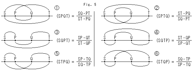
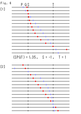 Fig. 5 above is the list of the six different cross ratio. Each cross ratio represents four cross ratio of the same value. In combination diagram the upper arcs are for numerators and the lower arcs are for denominators.
  ,
,  and
and  inth right row are reciprocal of
  ,
,  and
and  respectively. Therefore, three kinds of cross ratio are essential. Any cross ratio never change by projective transformation.
Fig. 6 shows positional relation between points P and Q on a straight line under fixed cross ratio. Straight lines are lined in rows. We plot the two points P and Q on each line. Points S and T are fixed.
[1]: We move the blue point P at regular intervals and let the red point Q follow it so that cross ratio is unchanged. At the upper left in the figure point Q looks getting freeze when point P passes point S to the left. At the right bottom point Q looks rapidly running far to the right when point P goes through the point T to the right a little.
[2]: This time we move the red point Q at regular intervals and let the blue point Q follow it. Their atitude is thoroughly inverse to that of [1]. [1] and [2] are congruent as a figure.
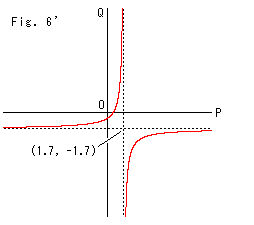
Fig. 6' widely shows the corelation between points P and Q in Fig. 6 using XY-coordinate. Curves drawn are hyperbola.
Cross ratio does not change if points P and Q move as shown in Fig. 6 and Fig. 6'.
Now let us see where cross ratio is applicable. And we will see how cross ratio relates to the other cross ratio as invariant (having common value).
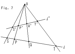 Fig. 7 shows the projection of four points S, P, Q and T on straight line
  to points S', P', Q' and T' on straight line
  with projection center O. In this porojection relation of cross ratio is
(S'P'Q'T') = (SPQT) .
In other ombination of four points are similar to this equation. Projection center O, segment ST and segment S'T' correspond to the camera, ground and Panel-screen that we saw in chapter 29.
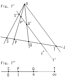 Fig. 7' shows a peculiar case. The slope of straight line
  is parallel with straight line OT, so that we can not draw their intersection as T'. But we assume the intersection T' exists at infinity. We can accordingly write


Therefore cross ratio (S'P'Q'T') on line  is equivalent to (SPQT), and it becames


This idea can be applied to a single point on a line. We describe a point q shown in Fig. 7'' with cross ratio


Point Q can not go over point T. Yes, it can. No trouble to jump across infinity! We will understand it later. The line to point T shall be drawn without dots.
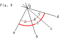
Fig. 8 shows four straight lines a, b, c and d that pass common point O. Such a bundle of straight lines is called pencil of lines. (It's not a writing pencil.) We can find cross ratio on a pencil though lines themselves have no value. Cross ratio of the pencil of lines a, b, c and d with angles shown in the figure is


Angles are to be measured counter-clockwise as positive wherever starting point is.
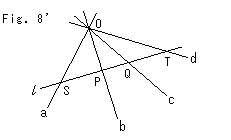
Look at Fig. 8'. An optional straight line  cuts pencil of lines a, b, c and d. Let points S, P, Q and T are intersections of them. Then the cross ratio of pencil can be described as
(acbd) = (SQPT) .
We may use this as adefinition of the cross ratio of pencil. If we reorder the left side alphabetically, it becames
(abcd) = (SPQT) .
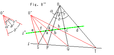 Also, from Fig. 8'' we instantly realize that
(abcd) = (SPQT) = (efgh) .
And we understand


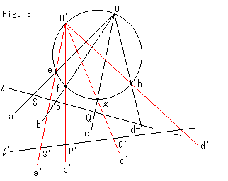 Look at Fig. 9. Four points e, f, g and h, and two points U and U' are on the circumference. And the black pencil of lines a, b, c and d, and the red pencil of lines a' b' c' and d' are drawn. For the time being let us denote the black pencil by U-pencil and the red pencil by U'-pencil for simple. Since angles viewed from point U to the four points e, f, g and h equal to those viewed from point U', the cross ratios of U-pencil and U'-pencil are the same. We cut U-pencil with straight line
  , and we get the sequence of points S, P, Q and T. Similarly we cut U'-pencil with straight line
  , and we get sequence of points S', P', Q' and T'. Cross ratios of these two point sequences are the same. That is,
(abcd) = (a'b'c'd') = (SPQT) = (S'P'Q'T') .
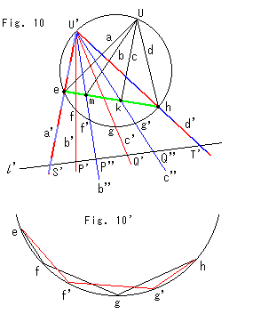 Look at Fig. 10. We cut U-pencil in Fig. 9 with the green line, and get the sequence of points e, m, k and h. Drawing of U-pencil under chord eh is omitted. We draw a new pencil of lines a', b'',c'' and d' with the center U'. This new pencil is colored in blue but lines a' and d' are common to U-pencil and U'-pencil, and so they are red and blue. Straight line
  cuts the new pencil, too, and gets the sequence of points S', P'', Q'' and T'.
Fig. 10' is the enlargement of circumference area of Fig. 10 excluding and pencils. We can make cross ratio with sequence of points on the circumference. We draw chords (not arcs) as shown. And we do it as if the sequence of points were on a straight line.
From these things,

and we understand that all of these cross ratios are the same.
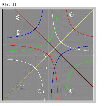
We saw what cross ratio is like. Now, which type of cross ratio listed in Fig. 5 is applicable to the definition of length? Let the value of cross ratio  be
be  , then


Fig. 11 shows variation of cross ratios on XY-coordinate when the value of cross ratio  changes. The center is the origin, and X-axis is
  and Y-axis is cross ratio. The gray lines are just for our observation. Well, we don't see which is good, do we?
Let us investigate the features of every type of cross ratio.
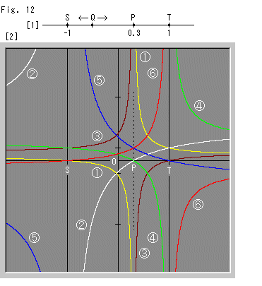
Look at Fig. 12.
[1]: We fix points S, P and T, and move point Q. The fixed location 0.3 of point P is optionally set. Points S and T are also optional but they sandwich point P as shown.
[2]: Some cross ratios diverge and change their sign at point S, P or T. But between points S and T (excluding both end points), the blue curve  and red curve
  neither diverge nor change their sign. And the red curve increases from zero to infinity monotonously. It is likely that we can utilize this cross ratio (STQP) of
  to define length. Cross ratio (STPQ) of blue curve
  looks also good if we decide the leftward is positive.
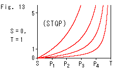 Fig. 13 shows how red curve
  of cross ratio (STQP) changes when the location of fixed point P changes. The shape of the curve depends on point P. It results that we can not use cross ratio (STQP) as it is for defining length. Cross ratio (STPQ), neither.
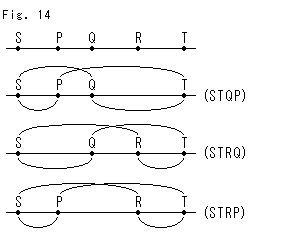 Look at Fig. 14.
There five points S, P, Q, R and T on a straight line. We make cross ratios (STQP), (STRQ) and (STRP) by picking up four points out of the five. The type of these cross ratios is  . The relation among them is


It can be expressed with parentheses,
(STQP)(STRQ) = (STRP)  (2).
(2).
This is multiplication. So let's change it into addition by using logarithm. It is only logarithm that can change multiplication into addition without limiting an interval. The base of logarithm is optional, and we use the base of natural logarithm.
Take logarithm of equation (2), then
log(STQP) + log(STRQ) = log(STRP) .
We are going to define (agreement) these logarithmic values as distance. Let us describe the new distance with brackets. Then distance [PQ] between two points P and Q can be written as
[PQ] = k log(STQP)  (3).
(3).
This [PQ] is to be signed. Constant value k depends on unit we use. And we describe
 [PQ] + [QR] = [PR]
  (4).
(4).
Consequently we can make addition and subtraction in ordinary way, provided that points S and T are set. To calculate backward from distance [PQ] to the ordinary distance PQ, Point P or Q must be given.
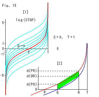
Look at Fig. 15.
[1]: We fix points S, P and T, and move point Q as shown. The red curve shows the logarithm of cross ratio (STQP) while point Q moves. We take constant k as k = 1. The sky blue curves are in cases when location of point P changes at regular intervals from the red curve. These sky blue curves are congruent though vertical intervals are not constant.
[2]: We enlarged the right part of [1]. We set three points P, Q and R, and we see the relations of distances defined above. The green belt is for observation. The shape of belt is a perfect parallelogram. And we understand equation (4) really works.
It looks like the theory that a deformed object regularly (linearly) appears if reflected by an awry mirror, doesn't it?
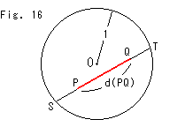
Look at Fig. 16.
Circle O is the circle of Fig. 3. There are two points P and Q in Circle O. The chord ST passes trough them. We measure the length of segment PQ as [PQ] by using formula (3). In this case, constant k is 1/2 because the radius of circle is 1, and


Since the relation between segment PQ and its length [PQ} is as sown in Fig. 15, the segment PQ never stick into the circumference whatever enlarge [PQ]. Therefore, we can regard the circunference as line at infinity.
It is Klein's disk model that uses such distance as hyperbolic distance. It is a metricised projective plane. The metrization here is not micro-scopic ds in Ch. 21 but global and macroscopic.
We can say that we first cut a disk out of a projective plane and then metricise it. Seeing Fig. 15, it seems that the metrization is to compress the whole projective plane into a disk. But, if it is true, we have to identify antipodal points of the disk. It reminds us that in chapter 4 we compressed a deformed plane into a disk. The compression corresponded to the metrization, didn't it? But we did not think anything about antipodal points.
Anyway, there is nothing outside the disk.
The difference between the inside disk and Euclidean plane is only that axiom of parallel lines. However, it is under the agreement such that we measure distance between points P and Q as [PQ]. And we say that things are congruent if their length are equal in this agreed measurement. The movement with keeping length is called isometric transformation.
Needless to say, "isometric" is a length measured by a certain definition.
The followings are some constructional examples of isometric transformation.
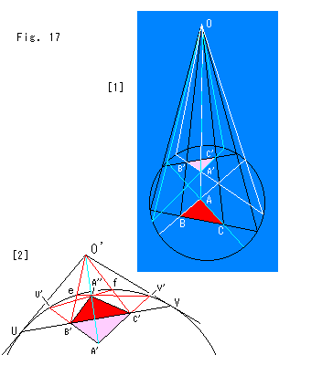
Look at Fig. 17.
[1] is drawn in the same manner of Fig. 4.
[2] is the construction that turns over (the front appears) triangle A'B'C' once again. The procedure is as follows.
1. Draw straight line B'C', and get intersections U and V.
2. Draw tangents to the circle at U and V, and get the
intersection (new projection center) O'.
3. Draw straight A'B', and get intersection U' on the circle.
4. Similarly get intersection V' on the circle.
5. Draw straight lines from point O' to vertices B' and
C', and get intersections e and f on the circle.
6. The intersection A'' of straight lines eV' and fU'
corresponds to vertex A'.
Straight line UV is the reflection axis.
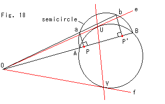
Fig. 18 shows how to get projection center O out of only two points P and its corresponding point P'. We used a hemisphere in Ch. 13 but here we use a semicircle. The semicircle and the model disk are on a single plane.
The procedure is as follows.
1. Get intersections A and B of straight line PP' and
the circle.
2. Draw the semicircle with diameter AB.
3. Draw perpendicular lines at points P and P', and
get intersections a and b on the semicircle.
4. Draw straight lines PP' and ab, and get the intersection,
that will be projection center O.
The reflection axis is the line that passes contact points U and V of tangents Oe and Of as shown with red lines.
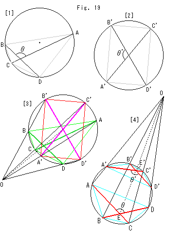
Look at Fig. 19.
[1]: Angle  is a hyperbolic angle in Klein's disk. We can get it by cross ratio,


Chords AB, CD, AD and CB in the right side are Euclidean length (>0).
[2]: We moved the intersection of diagonals of quadrilateral ABCD in [1] to the centeter of the circle. The new quadrilateral is rectangle A'B'C'D'. And angle  ' equals to angle
  . Since a hyperbolic angle and an Euclidean angle are equivalent at the center of disk, we can measure angle
  by using ordinary law of cosine considering the radius 1,


[3]: We draw [2] over [1] with rays. The projection center O is got by way of Fig. 18 using the center of circle and the intersection of diagonals AC and BD.
[4]: This diagram is drawn for easy to see. We can clearly understand that intersectional angles of diagonals of quadrilaterals are isometric. Relations with projective rays in [3] are the same as this [4]. Every interior angle is to be zero at a vetex on the circumference.
We have seen that the inside of disk is hyperbolic. Naturally we can clarify it by seeing that Lobachevsky's axiom of parallels is applicable or that curvature is constantly negative. But here we say "It is hyperbolic from global point of view." We have used neither differentiation nor integration.
Projective geometry has its own axioms. However, since we can get projective plane by adding a point at infinity or a line at infinity, axioms excluding parallel are in common use. In projective geometry there is no paralle lines from the beginning. Any two straight lines are to intersect at a point.
The defference between axioms in projective geometry and axioms in Euclidean geometry is as follows.
Projective geometry has infinity but not distance.
Euclidean geometry has distance but not infinity.
And
Hyperbolic geometry has both of (hyperbolic) distance and infinity.
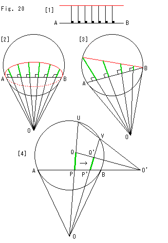 Look at Fig. 20.
We can also see that distance is hyperbolic by drawing equidistant lines (cf. Ch. 10).
[1] is on Euclidean plane. We put segments with constant length along the straight line AB. Every segment is perpendicular to straight line AB. The mark  shows Euclidean right angle. The red straight line connects the top end points of segments. Needless to say the straight line AB and the red straight line form Euclidean parallel lines.
[2] is Klein's disk. The red line is an equidistant line with respect to line AB. The equidistant line is an ellipse inscribed to the circle. It is not paralle at all neither in Euclidean nor in hyperbolic.
[3] is Klein's disk, too. The red line is hyperbolically in parallel with straight line AB.
Green segments that are perpendicular (hyperbolic right angled) to straight line AB connect the parallel lines. Their length are obviously not constant.
[4] shows how to construct an equidistant line. We use projections though we can draw it by calculation. Suppose that there is intersection O of tangents at points A and B and that segment PQ is on straight line OU as shown. The procedure to move segment PQ to the right and get segment P'Q' while keeping its length is as follows.
1. Choose point P' on segment AB, and draw straight line OP'V.
2. Get intersection O' of straight lines UV and AB.
3. The intersection of straight lines OV and O'Q will be point Q'.
For the next movement P'Q' to P''Q'' we will repeat 1. to 3. similarly.
By the way the parallel linens in [3] are not in consistency with Fig. 7'. Because distance in Fig. 7' is not defined. Points A and B in [3] are on the circumference that is regarded as the line at infinity. It is because destance is defined.
That is to say, draw a circle on an ordinary sheet of paper and measure distances and angles by using cross ratio as shown in Fig. 16, then the circle can be regarded as the disk model. It is what we have been doing. We have had no trouble without being aware of projective plane. Now the inside facts are exposed by and by.
We got Klein's disk. But where is other geometry? Various geometries should appear out of projective geometry. Only hyperbolic geometry came out smoothly. It must be the reason that we began with the circle of Fig. 3. We drew the circle without question. We should see the root, otherwise we can not feel at ease. Also, what about that projective plane is one-sided?
[Back] [Next] [Contents]
 Look at Fig. 1.
 Now we draw a unit circle (circle with radius 1) on a projective plane as shown in Fig. 3. We are going to make it into a disk model.


 Fig. 5 above is the list of the six different cross ratio. Each cross ratio represents four cross ratio of the same value. In combination diagram the upper arcs are for numerators and the lower arcs are for denominators.
 Fig. 7 shows the projection of four points S, P, Q and T on straight line
  Fig. 7' shows a peculiar case. The slope of straight line


 Also, from Fig. 8'' we instantly realize that
 Look at Fig. 9. Four points e, f, g and h, and two points U and U' are on the circumference. And the black pencil of lines a, b, c and d, and the red pencil of lines a' b' c' and d' are drawn. For the time being let us denote the black pencil by U-pencil and the red pencil by U'-pencil for simple. Since angles viewed from point U to the four points e, f, g and h equal to those viewed from point U', the cross ratios of U-pencil and U'-pencil are the same. We cut U-pencil with straight line
  Look at Fig. 10. We cut U-pencil in Fig. 9 with the green line, and get the sequence of points e, m, k and h. Drawing of U-pencil under chord eh is omitted. We draw a new pencil of lines a', b'',c'' and d' with the center U'. This new pencil is colored in blue but lines a' and d' are common to U-pencil and U'-pencil, and so they are red and blue. Straight line


 Fig. 13 shows how red curve
  Look at Fig. 14.


 Look at Fig. 20.