
Ch. 36 Mobius Strip (1) 
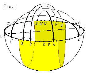 Two points at opposite ends of a diameter of a sphere are called antipodal points. On the edge of a hemisphere there are countless antipodal points. All antipodal points on the edge of the hemisphere made by central projection from the ground must be identified. That is, the ground that is spreaded infinitely has something like antipodal points. Such plane is projective plane.
Look at Fig. 1.
It will be a projective plane if we identify all pairs of them as shown with arrows. Though any visual model of the entire projective plane can not be made, we can get a part of it by cutting the hemisphere like the yellow belt. It is a well-known Mobius strip. Here we try to catch its character by fumbling an actual object.
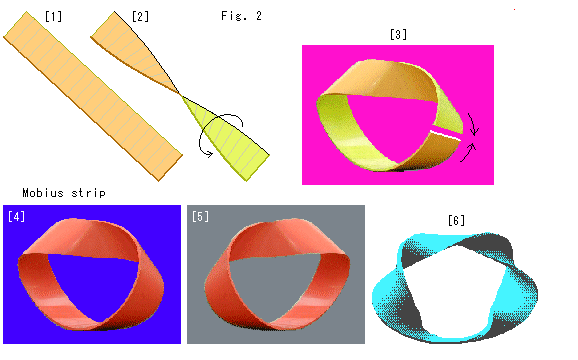 Look at Fig. 2.
You probably know how to make a Mobius strip. But let us see it first.
[1]: Cut a sheet of paper or rubber plane into rectangular strip. Some distortion is allowable except end lines.
[2]: Half twist (180 ) it.
) it.
[3]: Bend one end to the other. We can still tell the front side and back distinguishably.
[4]: Join both ends. At this moment, we can no more be able to say which is which side. Its edge is only one. This surface is Mobius strip. It is one-sided surface and nonorientable.
[5]: To make Mobius strip we can twist the belt clock-wise or counter clock-wise optionally. That is, both [4] and [5] are Mobius strips. But they are not congruent.
[6]: We may twist the belt as many as we want provided in odd times of 180 . The figure is one that is twisted 3 times of 180
 . It's Mobius strip, too. But here we use only a half twisted one.
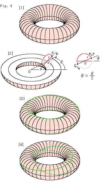 Look at Fig. 3.
It is not necessary for Mobius strip to be in beautiful balance shape. Any one-sided belt is Mobius strip. Its shape does not matter. However, we want to get one that is easy to calculate and convenient to observe. It can be obtained from a torus in donut shape.
[1]: A torus is usually drawn in the shape of donut. Its formula is


Fix R and r, and change  and
and  , then point P moves. Point P can be moved anywhere on the torus. In other words, the above formula (1) expresses the surface of torus.
[2]: We relate  and
and  in a way that


Then the route of P is fixed, and formula (1) becomes
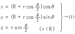

That is to say, point P makes a circuit of small circle o' when the center of small circle o' travels two rounds of large circle O. PQ is the diameter of circle o'. This formula (2) expresses the edge (singular) of Mobius strip because r is constant. But if we let  be constant which is smaller than R, and r be variable:

 formula (2) expresses the face of Mobius strip.
The ring of torus is like a tube with empty inside. We have a solid torus in mind now. The inside of ring of the solid torus is not empty.
[3]: The green curve is the locus of point P. The dotted line goes to the rear. Point P is on the solid line while point Q is on the dotted line, and point P is on the dotted line while point Q is on the solid line.
[4]: We turned [3] a little for easy observation.
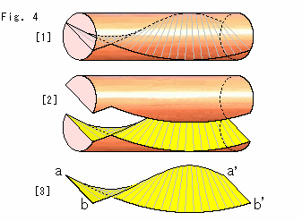
Look at Fig. 4.
[1]: We cut the loop of solid torus and stretch it as a cylinder to see how twisted the cut-out is. This cylinder can be separated by cutting along the cut-out. (The length of cylinder is shorten for drawing.) And we agree that both ends are equal as a loop.
[2]: We are removing the upper part.
[3]: We now get the cut-out without the cylinder. What joined a to a' and b to b' was in the solid toru.
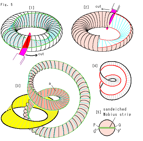 Look at Fig. 5.
We take Mobius strip out of the solid torus.
[1]: Mobius strip is lurking in the solid torus. We cut the solid torus along the green curve by the red knife as shown with an arrow. But the solid torus is not be separated into two. To get Mobius strip physically we have to scrape or melt the solid torus away.
Fomula (2) includes some relation between Mobius strip and a solid torus, but it says nothing about the idea of taking Mobius strip out of the solid torus. In abstraction or imajination it is possible to get the cut-out that is Mobius strip. But let us see physical matters a little.
[2]: It is on the way of cutting. We are doing it while throwing unwanted parts off. We will be able to get Mobius strip if we continuously cut the torus by two circuits.
[3]: Suppose the solid torus is rubber made. And we cut it without throwing anything off. We get the yellow Mobius strip and a long loop. The long loop is chained to Mobius strip and its length is double of Mobius strip. The dark surface a of the long loop was in contact with Mobius strip. We can not get Mobius strip alone unless we cut off the long loop.
[4]: We can color edges of surface a in red and black. Thus it is possible to distinguish the sides of surface a though Mobius strip is one sided. How come?
[5]: We cut the solid torus with red knife. It is completed by two circuits. If we start to cut from the upper part PQ, the red knife will come to lower side P'Q' at a circicuit, so that we have to continue cutting one more round. That is why the length of new torus is double. During full cutting, the red knife screws 360 .
.
This 360 is what we observed on the surface of Mobius strip. The observation direction changes every moment while traveling. And the red knife itself turns around the hole of Mobius strip two times. It is similar to that the earth moves round the sun, as it rotates on its own axis.
It is said that Mobius strip is twisted 180 , and actually we can make it
with a 180
 twisted-belt. But we have to make two circuits, 360
 twist if we fully paint Mobius strip.
That is, A surface glued to one sided suface has front and back sides, provided that we peel it off. We can see only one side of the glued surface if we leave it as is, even if it has the front and back. Well, our talk about the front and back of this cut-out is not so clear.
**************************************************
To know the character of Mobius strip we draw figures on it, we fumble Mobius strip itself, we put goods on it, and so on. We use Mobius strip applied formula (2).
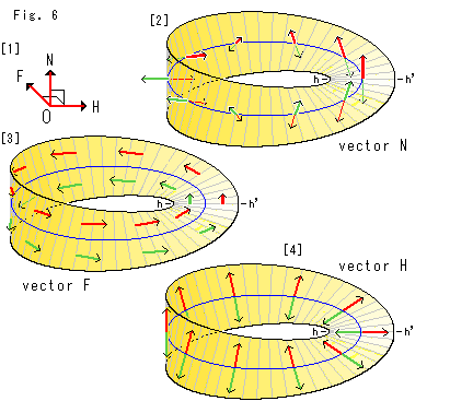 Look at Fig. 6.
First let us draw three kinds of vectors.
[1]: Let us name three vectors N, H and F. They are perpendicular each other. We put them on the face of Mobius strip. Vector N is a normal vector. Vector H and vector F are tangent vectors. Vector H is in the traverse direction and vector F is forward in the traverse direction while traveling Mobius strip. We color them in red for the first round and in green for the second.
[2]: A normal vector indicates the direction of face at a point. We move it along the blue center line from the start line hh' in counterclockwise. It turns upside down while it travels a round. And when it continuously travels one more round, it recovers itself. And two vecters are back to back at every point. Naturally we can not say which is which side. You may locate the start line hh' anywhere.
[3]: They are forwarding tangent vector F. Their course is apart from the blue center line. When red vector F made a circuit and comes back to the center line hh', it locates in the opposit side of the blue center line though its arrow direction is unchanging. The course is single but vector F never acrosses the blue center line. This vector F recovers itself at the second circuit, too.
[4]: They are traverse tangent vector H. Red vector H and Green vector H are back to back similarly to [1]. They are indicating opposte direction. Mobius strip is a loop. Doesn't it have the inside and outside distinguishably?
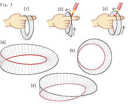 Look at Fig. 7.
The edge of Mobius strip is only one, and there is neither inside edge nor outside edge. However, it has the inside and outside as a loop. Let us see how the edge and the loop are related. We use Mobius strip which is not very soft.
[1]: We can certainly put our finger through the loop of Mobius strip as shown.
[2]: Turn Mobius strip while keeping the finger still. Color the edge which the finger touches in red.
[3]: Turn Mobius strip more with red coloring.
[4]: Finally we get Mobius strip with partially red colored edge. Where the finger rubbed was only this red colored edge. The red line jumps to the opposite side when Mobius strip is at [1].
[5]: It is a bird's-eye view of [4]. (It is shrunk for drawing.)
[6]: The figure is what we cut [4] at the left, and rejoined its cut-ends after untwisting. We may say that our finger was rubbing the inside of this red loop. But, in fact, the finger moved with cancelling the twist of Mobius strip. The loop of this [6] is distorted but not twisted as a whole. The black edge and the red edge are separated.
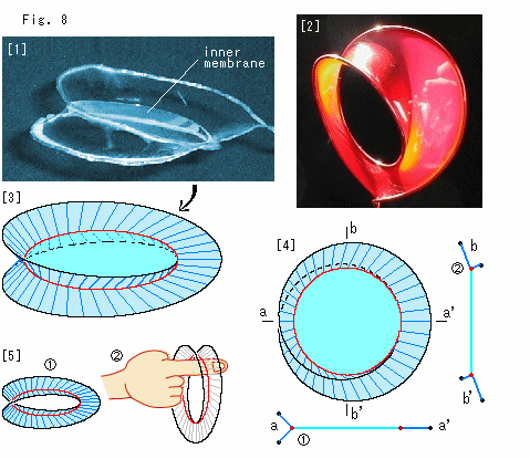
Well, we are confused a little by the above story. To see it cleverly, let us see soap film on Mobius strip just for a trial. What comes out?
Look at Fig. 8.
[1]: It is a photograph of soap film pitched on the wire frame of Mobius strip. The soap film intersects itsellf in Y-shape. It has the inner membrane as shown.
[2]: This Mobius strip has no inner membrane, and the upper part is curved in U-shape. The picture is copied from Membrane Structures in Web. It is beautiful, isn't it? But here we use [1] because the shape of face is simple and easy to see.
[3]: It is construced from photograph [1]. The soap film is colored in light blue and sky blue. The red loop is the line of intersection on the junction (Y-shape) of three faces.
[4]: It is the bir's-eye view of [3].  is the cross-section of aa' and
  is that of bb'.
[5]:  Take the sky blue inner membrane off, and we get Mobius strip with a face in "<" shape. (It is drawn by computer. The real soap film will be like photo [2] by tension if we break the inner membrane.)
  We put our finger throgh it. The finger tuches only the red line that is a single continuous loop. In other words , we may say that the red ridgeline is an inside edge of Mobius strip. However, it is not the edge of Mobius strip itself.
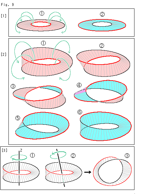 Look at Fig. 9.
We can easily exchange the inside and outside edges of a ring. What is the difference between an ordinary ring and Mobius strip? There are two kinds of surfaces. One appears to our own eyes at the beginning and the other appears when we move the object. We color the former in pink and the latter in sky blue. We also color edges, the inner in red and the outer in black. As to Mobius strip, we color its edge following [4] of Fig. 7. This time, the ring and Mobius strip should somewhat be soft.
[1]: It is a disk with the red hole.
 Twist the disk as shown with green arrows the red edge to outward and the black edge to inward.
 Then, we get a disk with exchanged edges. Its shape and size is the same as the original. New disk is turned over, but it is no problem because we can turn it over again ordinarily.
[2]: Now, Mobius strip.
 We twist Mobius strip as shown with green arrows, the red edge to outward and the black edge to inward. The way of twisting is the same as that of [1] but points we pick up for twisting are different.
 is what we twisted a little. We see the tiny sky blue portion at the left. When we continue to twist, it will be like
  ,
,  ,
,  and
and  in order.
 is what we twisted by 180
 . Its edge is the exchange of that of
  . And the sky blue face that we could not see at the beginning is fully in our sight now. Since Mobius strip has only one edge and one face, there is no difference between
  and
and  . Neithe can we say that it is turned over. Because Mobius strip has neither front nor back.
[3]: We can see any process of [2] by only turning Mobius strip without twisting. You may turn Mobius strip like  or
or  whicever. Mobius strip shows us its appearance in full of variety while turning.
  is one of them.
Let us see formula (1). To turn Mobius strip by angle  is that we change
  as
as


 +
+  ,
,
while to twist Mobius strip by angle  is that we change
  as
as


 +
+  .
.
It results the same whether we treat  or
or  because they are related in
  =
=  /2. We may also turn like
  of [3], not around Z-axis, but nothing changes because turning does not make any change in the shape. That is to say, Mobius strip never chanes whatever twisted or turned.
Thus characters of the disk and Mobius strip are quite different. However, if we do not distinguish edges and surfaces of the disk, we could say that the disk is unchangeable similarly to Mobius strip. On the other hand, if we define the front surface as the face we saw at the beginning, we could turn over Mobius strip, don't we?
It is completely different matter that we are not able to distinguish the front and back and that we do not distinguish them. A result depends on our definition of the front and back even if we intentionally distinguish them. For example, a flower vase is on the table with nothing around. A lady said to him "See the back side of the beautiful flower vase." He understood that he should see the surface that did not appear to him then. It is quite natural, isn't it? There was an unspoken agreement between the two of them, what the front and back were.
What we can not distinguish the surface of Mobius strip is judged by tracing it. A mark on the surface does not work. We can not distinguish the surface of Mobius strip wherever we mark.
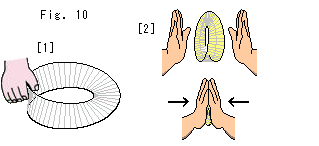 Look at Fig. 10.
[1]: We can grasp Mobius strip though it is one sided. It is because Mobius strip has both front and back partially.
[2]: We can perfectly sandwich the whole surface of a small sheet of paper between our palms. But we can not sandwich Mobius strip between our palms whatever it is small. Some parts of it remain as untouchable to our palms.
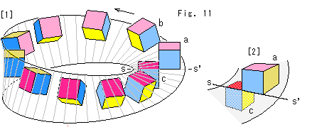 Look at Fig. 11.
[1]: We slide a cube on Mobius strip. It is colored in light and shade of red, blue and yellow. If one side is light, its opposite side is shade. Cube a is at the start line ss'. We move it while keeping the shade red face is always on Mobius strip. Cube b on thw way is showing the three of light colors.
[2]: Cube c that has traveled a circuit and now at the start line ss' again. Compared with cube a, it is upside down, right side left, and shifted to s under Mobius strip.
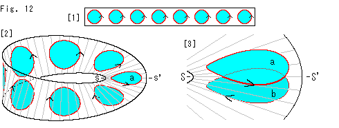 Look at Fig. 12.
How about a circl?
[1]: Sky blue disks are on a rectangular strip. The arrow on every red circumference shows that the red circle is so called a oriented circle.
[2]: It is Mobius strip made of the rectangular strip with sky blue disks. The surface of Mobius strip is twisted so that circles are distorted. Circle a is at the start line ss'
[3]: Circle b has traveled a circuit and now at the start line ss' again. Circles a and b are drawn with a little space from Mobius strip for easy observation. Circle b is upside down and the direction of the red circumference is in the opposite. Points inside the circle move as well as the circumference.
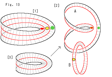
Look at Fig. 13.
Let us cut Mobius strip along its edge.
[1]: We mark red, yellow and green on Mobius strip as shown. The red line is to cut.
[2]: We get two entwined loops A and B. Loop A is the same thing as [4] in Fig. 5 though way of making is different. It has the front and back sides. The red mark you now see is the rear side of the red mark on Mobius strip [1]. Loop B is a new Mobius strip.
[3]: When we cut Mobius strip by one circuit, we get only loop A. That is to say, Mobius strip chages into a double-sided surface without cutting its loop.
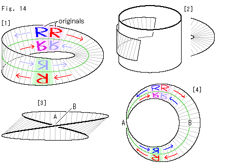 Look at Fig. 14.
Let us move letters and see details.
[1]: There are partial parallel faces on Mobius strip that is made by using formula (2). We dye them pink and light green. Bright red and blue letters "R" above the center line in the pink are set as originals. We move the red "R" clockwise as shown with red arrow and the blue "R" counterclockwise as shown with blue arrow. The red "R" turns by 180 when they come into the light green ground (our side). And it appears under the center line and the top and bottom is reversed. The right and left is reversed, too. The blue "R" is turned over, and the right and left is reversed as well.
We continuously move them to the original side making a circuit. This time, the red "R" turnrs over, and the right and left is reversed. The blue "R" turns by 180 , and the top and bottom is reversed without changing the face (back side). Both the red and blue "R" are turned over and upside-down. Their feet are on the center line from beginning to end.
The movment of letter "R" in clockwise and counterclockwise look different. It is because that the figure is drawn in the direction as if 180 revolution is done on the right half of Mobius strip.
[2]: The left part of Mobius strip looks to coil a cylinder when we put it onto a cylinder picture. And the right of Mobius strip looks like a slightly deformed consentric circle. Since we made drawings of Mobius strip and figures on it by using formula (2), the surface of Mobius strip must be twisted evenly. Neverthelees, why?
[3]: It is the view of [1] observed from the right. The surface of Mobius strip looks being twisted at our side B (the right side of [1]). But see nick lines crefully. In fact, the twist is started at A (the left side of [1]) and it is completed at B.
[4]: The bird's eye view of [1]. (It's shrunk for drawing.) Now we can comparatively and equally observe Mobius strip. This time, it seems that the twist is made at B. No, it's not. The face is vertical at A and is not twisted at the local area A. As you trace the circuit of Mobius strip with your own eyes, the twist is made by traveling the whole circuit.
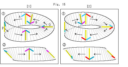 Look at Fig. 15.
We move an arrow shape instead of the letter "R". It results the same as above but we will see the difference between clockwise and counterclockwise.
[1]: In  arrow A is at the beginning and arrow B is at the last after making a circuit. Arrow B is turned over and upside-down. Arrow Q on the way is twisted 90
 (for half circuit) from arrow P.
  is the left view of
  . The twist in this view should also be made 90
 (for half circuit) while traveling from left to right. In mind set your eye in the direction of black arrow and follow it then you will find how twist. However, even if we do so, it is not easy for us to get at the truth though we know the twist is even.
[2]: We move the arrow shape in the opposite way. Well, it is neither easy to find the actual twist. We think we should used to.
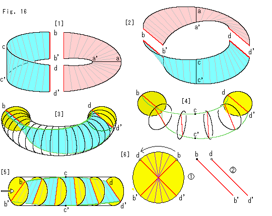 Look at Fig. 16.
Let us use a torus to see how we should control our eyes.
[1]: We cut Mobius strip into two and dye them separately, and mark them as shown to see which is which part. First we pay attention to the sky blue one.
[2]: We turn [1] so that the sky blue part comes in front of us.
[3]: It is a picture supposed that the sky blue part is in a solid torus. The torus is made of piled disks. We distinguish the front and back of each disk by shadeing. Say the bright yellow face is front ant dark yellow face is back.
[4]: The edge of Mobius strip and some disks are took out of the torus.
[5]: We stretch [4] and make it a cylinder, and we peep in it as shown the white arrow.
[6]: It is an enlarged view of the peep.
 The red diameter shows 90
 twist from bb' to dd'. Small circles at points b and d show that they are on the disk front.
 If the cylinder is not stretched but bended as torus, the disk with points b and b' faces us its back side. The diameter bb' is so turned and point b is marked in black. Now diameters bb' and dd' are parellel, and both points b and b' are upper side.
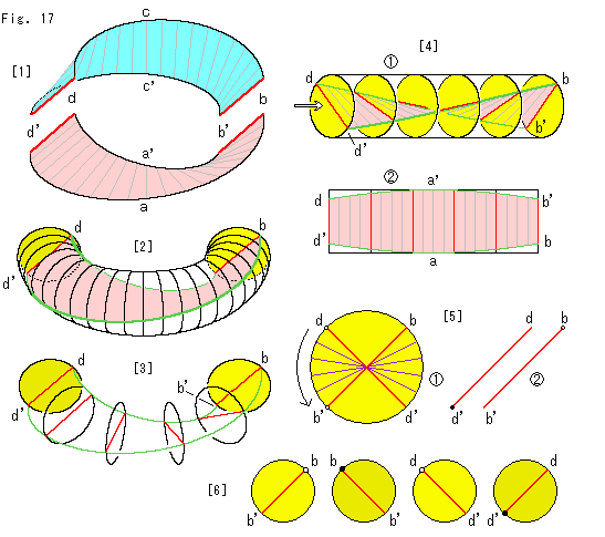
Look at Fig. 17.
Now let us see the pink part. We take the same procedure as above but we find different points.
[1]: We turn the pink part to us.
[2]: It is the inside of torus with the pink part. The front of disk appears at the right and the back appears at the left as well as the above.
[3]: The edge of Mobius strip and some disks are took out of the torus.
[4]: It is formed as a cylinder.
 dd' and bb' look like straight lines.
 The bird's-eye view of cylinder
  . Mobius strip looks the widest at nick aa'.
[5]: It is the peeped view of cylinder  of [4].
 It shows 90
 twist as well. But this movement is shifted by 90
 from that of Fig. 16. It's not 180
 .
.
 Segments bb' and dd' when cylinder is bended back to the torus. In this case they are in parallel. However, point b is at the upper side and point d' is at the lower side. This is the key point that differs from Fig. 16. And therefore, the movement of letter "r" and the arrow shape was questionable.
[6]: However, can parallel segments bb' dd' of Fig. 16 and dd'
 bb' of this Fig. 17 be jointed? Well, the answer must be "Yes" because we cut what connected. To make sure of it, we line disks up with those segments showing the front and back. Segments are surely jointed.
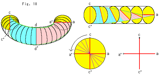
Look at Fig. 18.
Incidentally let us draw around the joint of the sky blue part and the pink part. The movement looks like the wing of an airplane which is getting back to safty flight after a sharp circling.
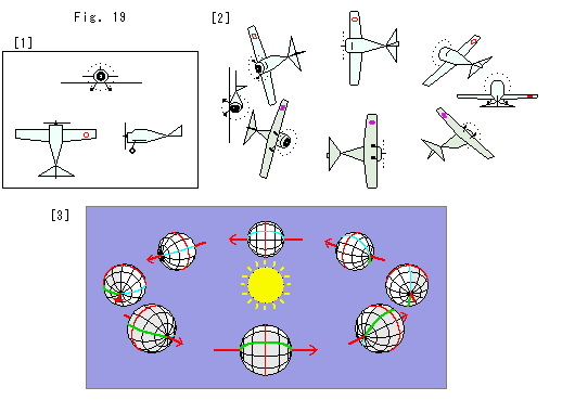 Look at Fig. 19.
[1]: It is easy for us to grasp the surface of Mobius strip if we imagine acrobat plane. We fly the propeller plane in the diagram.
[2]: The plane makes a circular flight while turning over. The plane must make even-numbered circuits, otherwise it can not take up the stance for landing.
[3]: It is the movemen of a planet. The central yellow ball is the sun. It may be useful to imagine such a planet. The orbit of this planet is the center line of Mobiusu strip. The red arrow is the axis of rotation. It is the orbital tangent so that there is no season. We on the earth have the Polestar that never move in the sky. But people on the planet have no polar star. And a year is half a day and two years a day. 24 hours is 2 years! The picture shows one year movement (a circuit). A man on the planet is making two circuits of Mobius strip everyday. The red curved line is the equator. The sky blue line is the date line and its oppsite line (dark green) is the prime meridian.
You might say that what we have seen is need less. When we first saw a picture of Mobius strip, we felt it understandable. But now we know it was unreliable.
By the way, it is possible to see an object from right and left, front and back, and top and bottom at a time if we use TV camera or like. But can you correctly understand it in a moment unless we are familiar with it?
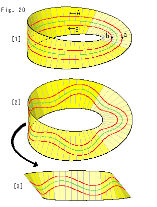
Look at Fig. 20.
Let us draw lines that travel along the loop of strip.
[1]: The green line is a center line. Suppose the red line expends counterclockwise from point a. And It turns back and arrives at point b which is the opposite side of point a. When the red line extends one more round, it gets back to the started point a. The red line never went across the center line. Nevertheless the red line runs both side of the center line. The red line looks like parallel lines when we see them partially. But it is not true. Route A and route B are actually a single route.
The green line looks a median or a central reservation on a road but it does not divide Mobius strip into two. If we cut Mobius strip along the green line, its length becomes double. There is no opposite lane on Mobius strip. We have no choice for traffic regulations but one way.
[2]: We deformed the center line in zigzag. But it resuls the same as [1].
[3]: The left side of [2] is not easy to see. So we turned and faced it to us as shown. Now we can see that the red line did certainly not cut the center line.
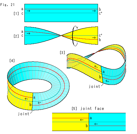 Look at Fig. 21.
We are going to see the situation on Mobius strip. But, first let us see what a straight line in finite region is. We draw a line in a rectangular strip, and then we convert it into Mobius strip.
[1]: We cut an ordinary sheet of paper in a rectangular strip, and draw a red line ab on it in parallele with its edges. The length of red line is so limitted by the rectangular that the red line is not a straight line but a segment. The arrows indicate direction of the segment for our observation.
[2]: We twist the rectangular strip by 180 . The yellow area is the back side of rectangular strip.
[3]: Bend fairly both ends of the twisted rectangular strip toward us. Join them and we get Mobius strip. Purposely we colored the portion that was the back side of rectangular strip though Mobius strip is one sided. It is to show which is which. The joint is our side but the opposite side is hard to see, isn't it? We cannot help but Mobius strip made of a sheet of paper or rubber forms like this.
[4]: We use formula (2), and re-draw [3]. As to the joint there is no condition in formula (2). We can set the joint line at any locaton by changing  .
.
The end points of red line do not meet at the joint line unless it is median. If we continue to stretch the red line in the same manner, it reaches point b at one more round. But such extra line is not on the rectangular strip.
[5]: We newly cut Mobius strip at the opposite side of the joint. And we untwist and unroll it, and get a new rectangular strip. Compare the new rectangular strip with [1] and [2] carefully.
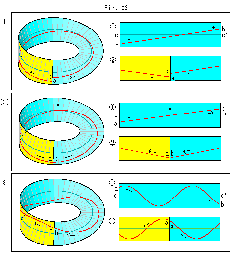
Look at Fig. 22.
Let us see how the red line becomes on the joint face. We follow the same procedure as above, rectangular strip are drawn shorter in length.
[1]: The red line crosses the center line.  is the original rectangular strip and
  is the joint face. The red line does not meet at the joint line.
[2]: It is a special case. The red straight line ab passes the center line exactly at its middle point M. Now distaces ac and bc' are equal, and the red line meets at the joint line as shown in  . But it is V-shaped and not smooth. Of cource the red line on Mobius strip is V-shaped though it is not seen clearly.
[3]: It is a sine curve. The red curve on Mobius strip may not look like so, but it is certainly a sine curve. We set the length of cc' of  by 3
by 3 (odd multiple of
  ). Then, the red line smoothly joints itself on the joint line.
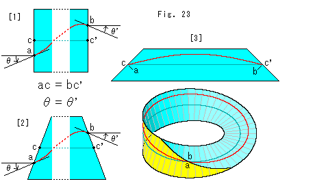 Look at Fig. 23.
[1]: It is what we got the above. Namely, the end points of red line on the original rectangular strip should be as shown for smooth joint on the joint line of Mobius strip.
[2]: It is not neccerary to be a rectangular strip for an original belt. A trapezoid also works for the smooth joint with the same condition as [1]. (A parallelogram or like does not work. Both the red line and edge are broken at the joint line.)
[3]: Let us make Mobius strip with a trapezoid belt. The red line is the upper part of a sine curve (0


 ). Its end points are exactly at the end points of center line cc'. It satisfies the above condition. So the red line smmothly meets itself on the joint line of Mobius strip.
Now, let's go to next chapter, and see far in the distance at infinity on Mobius strip.
[Back] [Next] [Contents]
 Two points at opposite ends of a diameter of a sphere are called antipodal points. On the edge of a hemisphere there are countless antipodal points. All antipodal points on the edge of the hemisphere made by central projection from the ground must be identified. That is, the ground that is spreaded infinitely has something like antipodal points. Such plane is projective plane.
 Look at Fig. 2.
 Look at Fig. 3.


 Look at Fig. 5.
 Look at Fig. 6.
 Look at Fig. 7.
 Look at Fig. 9.
 Look at Fig. 10.
 Look at Fig. 11.
 Look at Fig. 12.
 Look at Fig. 14.
 Look at Fig. 15.
 Look at Fig. 16.

 Look at Fig. 19.
 Look at Fig. 21.
 Look at Fig. 23.