
Ch. 37 Mobius Strip (2) 
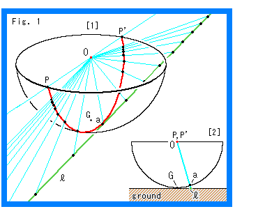 Now let us see the situation at infinity on Mobius strip. To do so, we use the hemisphere which we previously used in chapter 31.
Look at Fig. 1.
[1]: The red spot is the center of hemisphere O. The black point G is its bottom (south pole) where the ground plane touches. The green line  is a straight line drawn on the ground. The edge of the hemisphere O is the line at infinity. The sky blue lines are projection rays from the green straight line
  to the surface of semisphere. The red line PP' is the projected line that is a great circle. Point a is the middle point on line PP'. This red line PP' should be regarded as a straight line that stretches infinitely. We are going to see what happens if we put it onto Mobius strip.
[2]: It is the cross section passing three points O, a and G for clarifing their positional relation. They are always in the positional relation as shown. At this moment, point a is apart from point G and it is not on green line  . Naturally, in a case, point a is on point G and so is on green line
  .
.
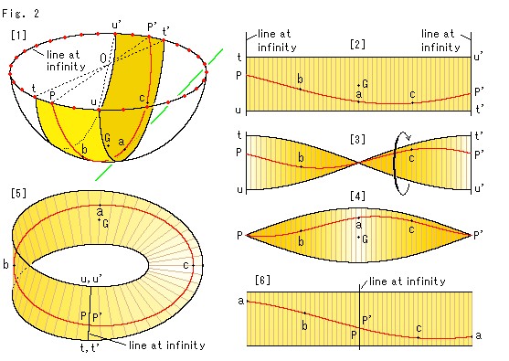 Look at Fig. 2.
[1]: The red spots on the edge (line at infinity) of hemisphere O show countless antipodal points. The dotted lines indicate that the end points of red line PP' (= straight line) are antipodal and points t, t' and points u, u' are also antipodal. We cut hemisphere O as shown. It is convenient for construction to cut hemisphere O in perpendicular to the equatorial plane. But you may freely cut hemisphere O as long as the red line PP' is in between lines tt' and uu'. Marks a, b, c and G are to trace points on hemisphere O to Mobius strip.
[2]: It is a rectangular strip taken from hemisphere O. We treated the cut-out as if it is rubber made, and smoothed it flat. Since both end lines, right and left are at infinity, we may regard the length of rectangular strip is infinity. But the lines at infinity is that we pllued in our hands!
[3]: The right end of [2] is twisted by 180 while the left is fixed.
[4]: It is a view from top of [3].
[5]: We jointed the end lines of [3] and got Mobius strip. The line at infinity is the joint line of Mobius strip, and point a is on the opposite side.
[6]: We newly cut Mobius strip at point a and flat it. This time, the red line is smoothly connected.
Thus we caught how a straight line that extends to infinity makes a loop at infinity. And the red "straight line" on Mobius strip that is curved surface keeps its character as a straight line.
No one knows whether the straight line acts like this at infinity or not. However, we feel nothing illogical. Naturally, It is based on an idea that there actually exists what is called infinity and a straight line can be stretched to that infinity.
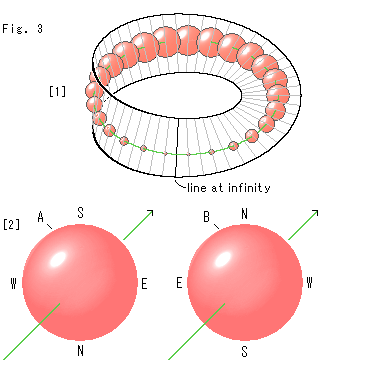
Look at Fig. 3.
What happens if an object that passes line at infinity has some volume?
[1]: We draw a green straight line on Mobius strip of skeleton. And we thread red semitransparent beads with the green line like a necklace. Every gap of balls, center to center in the figure, is equall for our eyes. But we can move it. The bead becomes smaller and smaller when it gets close to the line at infinity. The bead on the line at infinity has no size but it still exists there. It gets bigger again after passing the line at infinity. And it will be back in the original size when it arrives at the start point. Thus the size of any solid body on Mobius strip with the line at infinity changes its own size in our sight. It makes no difference wherever we set the start poin.
[2]: Ball A is the bead that is being at the start point. Ball B is the bead that has traveled a circuit. Compare ball A and ball B. The directons of their green arrows are the same.
But points N and S are reversed, and points E and W as well. Any object that has passed the line at infinity becomes like this. But, naturally, ball B will be restored to it's former state if it goes one more round. We found so much differences from previous drawings of finity, didn't we?
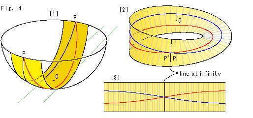 Look at Fig. 4.
This time we draw paralle lines.
[1]: We cut the hemisphere. The red and blue lines are parallel. They are drawn to sandwich point G at the middle for easy construction. Points P and P' are at antipodal points on the edge of hemisphere.
[2]: The parallel lines on Mobius strip. Points P and P' have become a single common point. And the parallel lines form loops perfectly.
[3]: It is the rectangular strip took from Mobius strip. It shall make sense if we regard the both end lines are identical in twist.
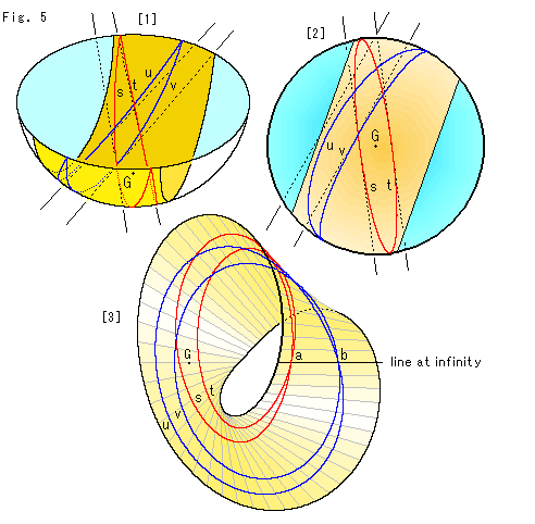
Look at Fig. 5.
Two pairs of parallel lines now.
[1]: We have to cut the hemisphere so widely that two pairs of parallel lines are contained. On the ground the red parallel lines are just under the hemisphere but the blue parallel lines are off to the side.
[2]: It is the bird's-eye view of [1].
[3]: It is Mobius strip made from [2]. It is drawn to show both of the line at infinity and the area where the two pairs cross each other are facing to us at a time. On the line at infinity, the red parallel lines meet at point a and the blue parallel lines meet at point b. The distance between points a and b is infinity though it is visible. Therefore we have to regard not ony the length but also the width of Mobius strip as infinity. There is no ordinary distance on the line at infinity
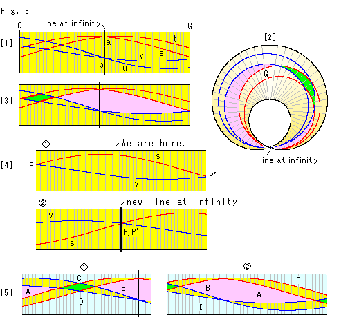 Look at Fig. 6.
[1]: We shrunk and cut Mobius strip in Fig. 5, and got the rectangular strip. The central black line is line at infinity. Both end lines are at G.
[2]: The top right area of Mobius strip in Fig. 5 is not clearly seen. So we drew it with line at infinity in perpendicular to us since we have uderstood around line at infinity. As colored in green and pink, there appears two quadrilaterals. But the pink one is not easy to see as a quadrilateral, isn't it?
[3]: We shifted line at infinity of [1] a little so that the two quadrilaterals are in the rectangular strip without dividing either of the two into parts. Any two pairs of parallel lines can be drawn like this. On an ordinary plane two pairs of parallel lines make one parallelogram. On Mobius strip we find the pink quadrilateral besides the green one. The pink quadrilateral is infinitely large and is laide across line at infinity.
[4]: Let us change our view point.
We agree for the present that two straight lines that meet each other at infinity are parallel. On that basis, we pay attention to the red straight line s and the blue straight line v.
 The rectangular strip is the same as [3]. The straight lines s, v intersect each other at points P and P'. They are not parallel lines, of course. However, there comes out a strage phenomenon if we exchange our stand point. Suppose that line at infinity is an ordinary location where we live now. Then where points P and P' stay shall be at infinity. And the end lines of rectangular strip are a new line at infinity where points P and P' are located. The two straight lines s and v intersect each other at this new infinity. Therefore two straight lines are to be parallel.
 shows the new situation with new line at infinity which is located in the middle.
Well, is it logical? What in un-paralle became what in parallel! However, it is true. They say "It is a character of what is called line at infinity." Wait a minute. It's funny for us now. Let us think of it in course of time.
[5]: The colored quadrilaterals in [3] are taken out together with their around.  is of the green quadrilateral and
  is of the pink. The domains C and D in sky blue ground are neighboring on Mobius strip. If we expanded the width (vertical length of the figure) of the rectangular strip to infinity, we could see the entire situation of the domains. Alternatively, in order to see them we may cut the hemisphere in a different direction and make another rectangular strip. However, it is not necessary for us to make such rectangular strip because we can easily guess what C and D are, provided that we must imagine that the width of the rectangular strip is infinity.
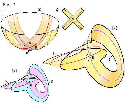
Look at Fig. 7.
We deform Mobius strip and try to see relations of A, B, C and D in Fig. 6 at a time. We use two lines as a substitute for two pairs of parallel lines for easy observation. The green parallelogram in [5] of Fig. 6 disappears into the intersection of the two lines.
[1]:  We cut the hemisphere in X-shape so that both the red line and the blue line are just in the cutout as shown.
  is the cutout.
[2]: We twist the X-shaped rectangular strip and joint the end lines as shown. It is the same as two Mobius strips glued back to back. The two black lines f and g taversing branches are line at infinity at joints.
[3]: It is colored corresponding with [5] of Fig. 6. The domains A and B are adjacent through line at infinity, and so are C and D. We can travel from A to B by crossing either line at infinity f or g. But we can never get to C or D unless we go across the red line or the blue. The domains C and D are similar condition. Well, nothing is new with the X-shaped rectangular strip. It is the same situation as that of [5] in Fig. 6, though we fairly see all of A, B, C and D.
**************************************************
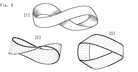 Let us see what differences between a paper-made Mobius strip and that of the formula are.
Look at Fig. 8.
[1]: It is one of appearances of a paper-made Mobius strip. We can see how it is twisted, but it is not very useful to see things on the surface. First of all, it is not easy to set up coordinate axis. In addition to that, there are some other reasns why we feel difficulty eith paper-made Mobius strip.
[2]: Turn [1] a little, then we can see the twisted part clearly. The gray regular nick lines are fairly perpendicular to the whole edge.
[3]: We turned [1] more. Now we can see that the strip is twisted three times. Two of twists are in the same direction and one in the opposite direction, and totally a single twist in net. This Mobius strip hides the surface so much with extra twists. That is why the paper-made Mobius strip is no good for observation.
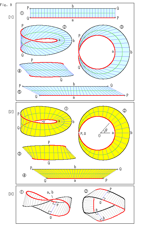
Look at Fig. 9.
Let us see relations between a rectangular strip and Mobius strip made with the formula.
[1]: It is in case that the length of edges of the rectangular strip is identical to that of Mobius strip.
 We nick the rectangular strip into n equal parts, and draw the green center line. Points P, Q are to be connected for Mobius strip so that they are marked with
  for attract attention. One side of the edge of rectangular strip is colored in red to see which is which part on Mobius strip.
 The nick lines are broken at the center line. They shall be smoothly curved if we draw them accurately. But we omitted on purpose for attract attention. Compared with the rectangular strip.
 , the figure is enlarged.
 It is a bird's-eye view.
 It is the view around points P, Q from the left. Nicks are leaning to one side. Only nick ab is perpendicular to the edge. It is quite different from paper-made Mobius strip.
 Points on the edges and center line of the rectangular strip
  and Mobius strip correspond each other. But the length of their nick lines are quite different except nick ab. So we shifted edges of the rectangular strip to right and left as shown. Now we possibly say that the length and angles of nick lines on the rectangular strip
  and Mobius strip are identical. However, if we make a paper-made Mobius strip with this kind of parallelogram, it will have no smooth edge but a cusp at the joint.
[2]: This time, first we draw Mobius strip, and then we cut and open it as a rectangular strip.
 The green center line is a circle. Its center is O. Every nick line is perpendicular to the green center line at regular intervals of n division which is similar to [1]. Nicks may look coarse but the numer of them is the same as that of [1].
 It is a bird's-eye view.
  is the angle of nicks. See Fig. 3. In [1] lengths of the red edge and black edge are the same as well as the rectangular strip. But in [2] it isn't. In the figure the length of black line is one and a half times as long as the red line.
 It is the view around points P, Q from the left. Nick PQ is perpendiculer to the edge. So is nick ab.
 It is what we cut and opened Mobius strip while keeping the length of edge with nicks. It is formed into a trapezoid and the length and slope of nick lines are distorted.
[3]: It is Mobius strip made of a rectangular strip sheet of paper. Its edge is dyed in red and black correspondingly to the rectangular strip. Just for a nice look, the number of nick lines is increased.
 Naturally, all nick lines are equal in length and they are fairly perpendicular to the edge. And the length of red and black edges are equal, too.
 We turned Mobius strip
  so that we can see around nicks lines PQ and ab at a time. Now we recognize that the situation of them are the same.
Points on Mobius strip and a flat belt can be correponded to each other by one-to-one mapping. It has nothing to do with the shape of Mobius strip or the belt. However, their partial density or like of points is never be equal. Paper-made Mobius strip also has some expansion and contraction though we can not clearly see it with our own eyes.
Let us name the red edge P-a-Q of Mobius strip in [2] "a small turning edge" and the black edge P-b-Q "a big turning edge". By this naming, we can say that paper-made Mobius strip has neither a small turning edge nor a big turning edge even though it has color-coding. This is the base of proportional beauty.
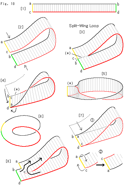 Look at Fig. 10.
[1]: Let us distinguish edges of a belt as shown.
[2]: We bend an end of the belt and true up the edges of them in flat. And we push the bended belt and glue touched portion.
[3]: Then, we get a loop with a split. The dotted line (*) is the joint. It is called Split-Wing Loop, though it does not appear in a mathematical book.
Split-Wing Loop does not look twisted anywhere. But it has neither the front nor the back, that is one-sided. You will see it by following the surface. Is it really twisted?
[4]: Forld Split-Wing Loop, and glue the yellow side ac and the green side bd as shown with arrows. Now we can surely see the twist. It would result that double twist (360 ) is made if Split-Wing Loop is twisted. It is doubtful, isn't it?
[5]: We turn [4] and expand its hole to see how twisted. The width is shrunk a bit for drawing. It is twisted only one time as we expected. When we cut the joint (*) and open the hole wide, we get an ordinary Mobius strip.
[6]: It is only the edge of Mobius strip. It is colored similarly to Split-Wing Loop of [3]. Obviously, the edge of Mobius strip is the same as that of Split-Wing Loop. Namely Split-Wing Loop is twisted. Then, how on earth, what was actually done in the process from [3] to [4]?
[7]: Let us see the trick.
 Let us begin with [2]. We slide the side ac onto the side bd. This formes an untwisted Split-Wing Loop, that is an ordinary cylinder.
 Turn over the face with the side ac. And glue this reversed side ac on to the side bd, then we get [4]. That is, in the process from [3] to [4], we canceled twisting and newly twisted in the different manner. You may omit the joint (*).
[8]: The side ac is slipped from the side bd but point c and its neighborhood are glued onto the face with bd. In this case the twist of Split-Wing Loop is not untwisted yet. Therefore its surface is still one-sided. We can see it by following the face as shown arrows.
 Mobius strip can be made by cutting a torus. So let us try some different cuts.
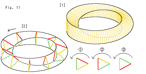
Look at Fig. 11.
[1]: Sometimes it is called a twisted triangular prism. A single surface is twisted and a hollow is formed. The ridgeline is single, too. The surface looks similar to that of Mobius strip but it is not so. The inside and outside are the front and back respectively. We can see only front side if the inside is the back. We can see only one side. That is why we feel something like Mobius strip.
[2]: The cross-section of loop is a regular triangle. This triangle turns as  ,
,  and
and  every circuit by 120
 each, and gets back to the original location by three circuits.
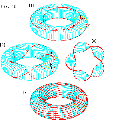 Look at Fig. 12.
[1]: Let us see vertices of the twisted triangular prism in a solid torus. The red line is the locus of the cut. It travels three circuits. The dotted red line is on the invisible back side. The dull yellow ring is a cross-section of the tube. The black spot a and two tiny circles b, c on the yellow ring are points are vertices of a regular triangle. The red line started from the black spot a gets back to the left lower point  at the first circuit and passes the right lower point c at the second circuit. And it returns to the black spot a at the end of the third circuit. The surface of this loop is twisted 120
 every circuit. Since the twist is not 180
 , the surface is not Mobius strip, of course.
The red curve makes 3 circuits with 1 turn. Say, 3 circuits 1 turn. With this wording, the simplest Mobius strip is 2 circuits 1 turn.
[2]: As a trial we made 2 circuits 5 turns. Point b is located exactly at the opposite side of a. The red line passes point b at the joint of the first and second circuits. Therefore we can make Mobius strip with 5 twists (180 x 5) when we cut the torus along the red line on the first circuit and the second circuit through the center of tube.
[3]: It is the bird's-eye view of Mobius strip taken out of [2]. The dotted lines are parts where were beyond the tube of torus.
[4]: The width of Mobius strip is limited. It is inconvenient for us. How about a torus with twisted surface? Red lines indicate how twisted. It seems convenient. But, first of all, the torus has front and back surfaces. It never change whatever twisted. Do not forget that we sometimes see torus from its inside.
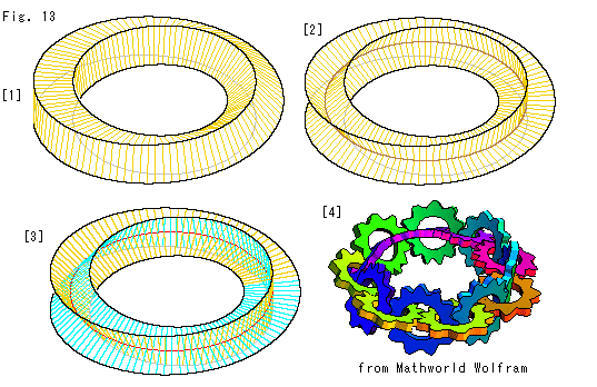 Look at Fig. 13.
[1]: It is twisted 90 a circuit. Its section is a square. You may call it a twisted quadragular prism.
[2]: It also is twisted 90 a circuit. But the surface cuts itself orthogonally all the way. The section is cross-shaped. But the black frame is the same as that of [1]. The surface twists 180
 by two circuits, but we are bewildered if it can be called Mobius strip or not, aren't we?
[3]: It is a transparent view of [2]. The color of the second circuit is changed for easy observation.
[4]: Gears in a row are on the surface of [2]. It is copied from Mobius Strip in Mathworld Wolfram. You should click and visit the web site. You shall be impressed by moving gears. And you must feel what function a twisted surface has.
Also there is a moving Mobius strip in A HREF="http://www.palmyra.demon.co.uk/illusion/geometry/geometry.htm">Mobius animation. M.C. Escher drew Mobius strip with ants on it. Those ants are actually crawling in RUBAN DE MOBIUS.
Well, there are lots of things about Mobiusu strip. But let us go back to projective geometry anyway.
[Back] [Next] [Contents]
 Now let us see the situation at infinity on Mobius strip. To do so, we use the hemisphere which we previously used in chapter 31.
 Look at Fig. 2.
 Look at Fig. 4.
 Look at Fig. 6.
 Let us see what differences between a paper-made Mobius strip and that of the formula are.
 Look at Fig. 10.
 Mobius strip can be made by cutting a torus. So let us try some different cuts.
 Look at Fig. 12.
 Look at Fig. 13.