
Ch. 39 Crosscap (1) 
 We can not to see whole of the projective plane with Mobius strip, whatever we try. However, there is a model called Cross-cap that shows the projective plane entirely. Let us see what it is.
Is it true that Cross-cap is obtained by sewing a Mobius strip to the edge of a disk?
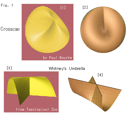
Look at Fig. 1.
[1]: Cross-cap is a curved surface as shown. It is actually not a plane. But, needless to say, we regurd it as flat. And Cross-cap is one-sided as well as Mobius strip. The picture is a copy taken from Surfaces. We can see it when we pick up a soft ball with the tongs.
[2]: It is a view of the front.
[3]: It is called Whiteney's umbrella that shows the top portion of Cross-cap. The picture is a copy taken from topological zoo. It might be nice if you have it up together with your friend.
[4]: It is the upside-down of [3]. It is copied from Teoria de Singularidades. Such crossing is called self-intersection.
First we see how to make Cross-cap. Then we see how it is similar to and different from Mobius strip.
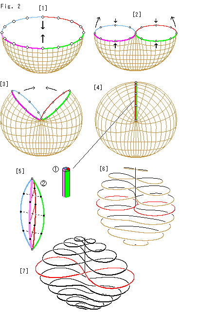
Look at Fig. 2.
[1]: We color the edge of hemisphere as shown, and we think about the four parts. The circle marked on the edge are representation of countless antipodal points. We suppose the hemisphere is rubber made, and joint a pair of antipodal points as shown with arrows.
[2]: The pair of antipodal points is sticked. Pull and turn up the right and left sides of the edge while pressing the front and back.
[3]: It is on the way to close the opening. We are going to joint the four parts of the edge, green to blue, and red to pink respectively.
[4]: Now we bundle the four parts and glue them as a segment. Let us name this segment Line of Self-intersection. It consists of four folded parts, the green, blue, red and pink. And the hemisphere became a closed surface without edge. Thus we get Cross-cap.
[5]: It is the situation at Line of Self-intersection. Line of Self-intersection is a single segment but we loosen it by force as shown. The green and blue pair up each other, and so the red and pink. The dotted lines express their connection. Line of Self-intersection is the line at infinity. But it is a folded loop.
[6]: It is an inside view of Cross-cap. The loops and figure-8 loops are made by horizontal slicing. The red curve is located at the bottom of Line of Self-intersection.
[7]: The reason why we used the hemisphere for constructing Cross-cap is due to our histry. We put a hemisphere on a infinitely spreaded plane and projected the plane to the hemisphere. And we regarded the edge of hemisphere as the line at infinity. Thereby, we had to identify anipodale points on the edge of hemisphere. That's why we used the hemisphere.
However, it is not difficult to draw a picure like [6] without using a physical property. We can apply one of formulae of a figure-8 curve. This [7] is drawn by using the formula called Cassinian oval with minor modification. We can get Cross-cap by covering up such frame.
 Look at Fig. 3.
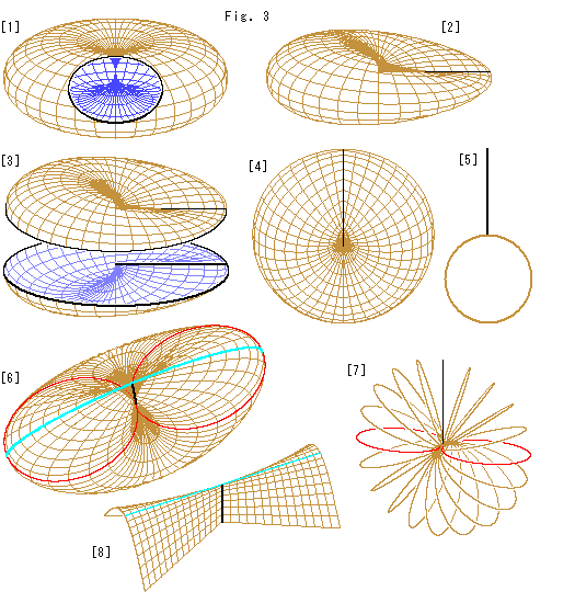
Here we use a torus without hole for Cross-cap. We can get the torus without hole by blowing the tube of ordinary torus or by sticking the pair of antipodale points of a ball.
[1]: It shows the inside of a torus without hole. The upper and lower are connected at the central point.
[2]: We can get Cross-cap immediately by denting the torus along one of radii as shown. The dented line is Line of Self-intersection.
[3]: It is the inside of Cross-cap.
[4]: The front of Cross-cap is turned to us. The top of this Cross-cap looks sunken slitely because we drew it with little slant. The grid on Cross-cap corresponds to [1] and it is different from that of Fig. 2.
[5]: It is the cross section that cuts [4] perpendicularly to the picture.
[6]: It is a slanting view from top. The picture is somewhat enlarged. The sky blue line is the ridge. The red line is the horizontal cross section that passes the center. The black Line of Self-intersection looks shorten because Cross-cap gets fat under the center as shown in [5].
[7]: It is the inside view of Cross-cap. The loops are made by slicing like a waterwheel. They are ellipses that get thinner as they go up. At the top it will be Line of Self-intersection.
[8]: The narrow part of top of Cross-cap can be drawn as Whiteney's umbrella. The sky blue line is the ridge. It is certainly a straight line. But we can see byond it a little. That is why the top of [4] appears with a little dent.
Thus we got Cross-cap. The grid on it can not be applied for changing points on a hemisphere to it. Because the character of curved surface is different from that of the hemisphere. But we leave it now, and we understand that the grid is a pattern for 3-D look. Cross-cap can be deformed just like rubber-made produt as well as Mobius strip.
 Look at Fig. 4.
We are familiar with rectangular strip that forms Mobius strip. Now let us make Cross-cap from the recutangle.
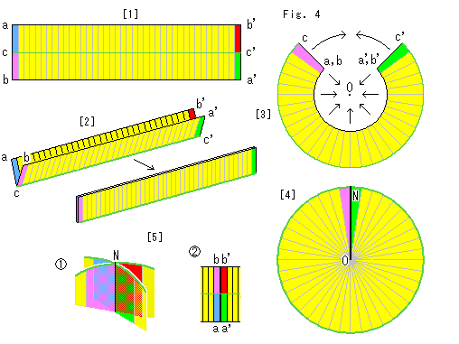
[1]: It is an ordinary rectangular strip with colored ends. The green line cc' is the center line.
[2]: Fold the rectangular strip longitudinally along the green center line cc' as shown.
[3]: Make the folded rectangular strip round, and pull the inner edges to a point O as shown with arrows. The center line cc' is the outer circular edge now.
[4]: Finally we get a disk. This disk is not a single face. The front and back are partitioned into two by the green circumference that was the center line of the rectangular strip. The black radius NO is the joint of [3]. We make it to correspond to Line of Self-intersection. That is, this disk is a pressed Cross-cap.
[5]: The top N of [4] is like  if we split it and peep the inside. It is the same situation as the joint of the rectangular strip ends after 180
 twist. That is to say, The joint (Line of Self-intersection) NO is the special line-domain where the rounded rectangular strip twists 180 in a moment.
If we blow the yellow disk up while keeping radius ON as it is, we will get Cross-cap. But the flat disk is quite useful in many cases since the joit works as Line of Self-intersection. Let us call the disk Flat Cross-cap.
**************************************************
 Now let us observe the character of Cross-cap.
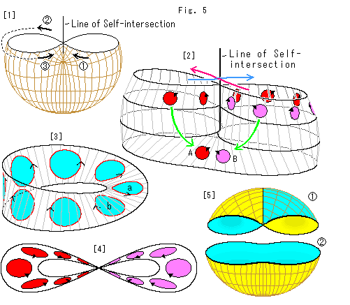
Look at Fig. 5.
[1]: The upper part of Cross-cap is cut off so that we can see how it works. When we go across Line of Self-intersection from , we come to the rear side  and turn to the front side
  as shown with arrows. Now compare two arrows and in the front. They indicate opposite direction each other.
[2]: We took out the upper part of [1]. The vertical nick lines are not the grid of [1]. They devide the four crosssections at common regular intervals. They are just for our observation.
First look at disks in a row. We move one of them from the left and let it go across Line of Self-intersection as shown with the blue arrow. The disk gets round and back from the right. Now the disk is turned over and its arrow indicates that the circumference direction is rversed. Let's move the disk continuously and go across Line of Self-intersection again following the red arrow. The disk moves like - - in [1], and gets back to the start point. The returned disk is the same as that of the beginning. It is the same situation when we move a disk two circuits on Mobius strp. The red and blue arrows do not make a crossing with an overpass or underpass. The two arrows show only moving directions, even if they have a common point.
Disk A is the original and disk B has passed Line of Self-intersection only once. The front and back of disks coexist on a single surface!
[3]: Let us compare it with Mobius strip. The sky blue disk a is the original and the disk b has made a circuit. The disk b is turned over and located the opposite side. We can say which side is which by part though the whole of Mobius strp is onesided. However, it is not always necessary for us to distinguish one side to the other because the surface is only one whether it is onesided or twosided. Therefore, the front and back of disks coexist on Mobius srip also. Namely movement on Cross-cap is the same as that of Mobius strip.
Movement on Cross-cap is allowed only on its surface as well as Mobius strp. And, before you say orientable or non-orientable, it is originally a single surface.
[4]: It is a bird's-eye view of [2]. The all front of disks appear on the left and the back on the right. On Mobius strip we come to the opposite side of its surface after making a circuit. On Cross-cap, however, an opposite side or inside does not make sense. Every disk goes to the right after the left circuit and goes to the left after the right circuit, making a figure eight. Therefore the right and left parts of [4] correspond to the surface and its opposite side (the second circuit) of Mobius strip.
[5]: Let us color Cross-cap. We devide Cross-cap into two. as shown. The upper is with Line of Self-intersection. We colored it yellow and sky blue on purpose to distinguish the front and back. The lower has not Line of Self-intersection. So we can color it ordinarily. But, it causes us not to color the whole of Cross-cap.
Naturally it is due to the fact that we distinguished the front and back. It ia agreeable that the surface of Cross-cap is neither the front nor the back but a face. Well, where did the front and back disappear?
This trick must be in Line of Self-intersection. The front and back are not to disappear. Originarily Cross-cap does not distinguish its own surface, front or back. And no one ask a question about it. It is somewhat different from that Mobius strip has no front and back (onesided).
 Look at Fig. 6.
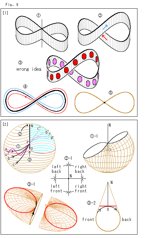
[1]: Let us see the figure-8 zone only.
: The crossing is Line of Self-intersection, where we can turn neither left nor right.
: So we may imagine the crossing as an overhead crossing, may not we?
: No, we may not. It is a wrong idea. Because it does not fit in with [4]. Compare moved disks on the overhead crossing with those of [4].
 : It is a bird's-eye view of. Don't guess that the movement is like the red line or the blue line. We can not go in and out of Cross-cap. It is a wrong idea, too.
 : To determin the rules of crossing, all we have to do is not to distinguish the front and back. We say again that it does not matter regardless existence or nonexistence of them. You see, we have not well clarified that Cross-cap is onesided. Therefore, for convenience�f sake we regard Cross-cap as a physically closed surface so that we can not get its inside without making a hole. What we intentionally do is only identifying points on Line of Self-intersection. The identification means that one sees oneslf there and they are exchangeable. Because one is oneself just like one in a mirror. (See also later chapter "Paper Craft".)
[2]: The traffic regulations at Line of Self-intersection is settled. But it is only for a neatly traverse. If not, what will happen?
: The upper right of the front surface of Cross-cap is taken off. The striped lines are horizontal, and the red line passes the bottom end point O of Line of Self-intersection NO. Now we start from the lower left and go straightly toward point P on Line of Self-intersection NO like a, b and c. When we arrived at point P, our courses change to the back side, and a to a', b to b' and c to c'. Even if we zigzag from u to point P, our course shall be u-P-u' as shown in purple. Crossing angle doesn't matter. -1 shows the section of Cross-cap that is cut by a slant plane. The right and left of cut-out are not symmetry but forming figure-8.
: Suppose we started from the front left and came to the top N of Line of Self-intersection NO. A figure-8 section is shrunk at the top N. We can find no figure-8 section there. First of all, there is no section there. There is neither front side nor back side at the top N. Which way should go we go? Well, we have an answer already. We are using the idea without awareness of it. -1 indicates the full directions. That is, we should go to the right back.
: Suppose we came from the front just below the bottom end point O of Line of Self-intersection NO. Which way can we go? If we have come from the front left, we should go to the back right. If we have come from the front right, we should go to the back. But we arrived at point O from neither right nor left, and we can not find any partner for the identification. We cannot walk on Line of Self-intersection NO because partners for the identification are defined. Say
Closed to traffic on Line of Self-intersection
As shown -1 we cut Cross-cap vertically at the center that is neither right side nor left, and we peep the cut-out from the top. Two red loops pass the bottom end point O of Line of Self-intersection NO. Line of Self-intersection NO and the cut line are drawn on the left part. We put up the left part and observe the section from the right. -2 shows it. Now we can pass point O without choosing any identification partner. That is, we go on the cutout line and reach the back side as shown with the arrows. Once we get in the back side or leave point O, we are free to go anywhere. Well, needless to say, point O is a point. So, in practice we can take any course except Line of Self-intersection NO.
Now movement on Cross-cap is perfectly completed.
 Look at Fig. 7.
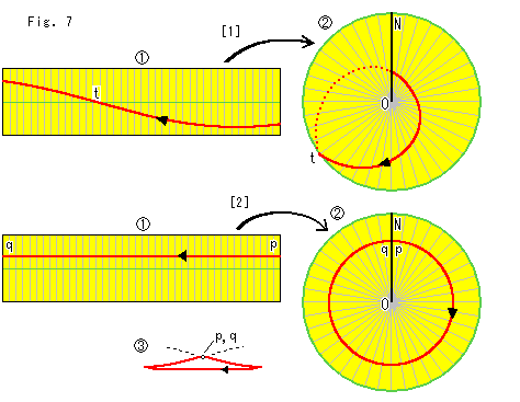
We move curves on a rectangular strip onto Flat Cross-cap. How do they look?
[1]: The red line in is a great circle taken from the hemisphere. The black arrow is for a easy observation of the flow of the red line. The green line is the center line. The red line goes across it at point t. The red line on the Flat Cross-cap turns to the rear side at t on the circumference, and it reappears at Line of Self-intersection NO. And it forms a loop.
[2]: Now we draw a red straight line pq on the rectangular strip in parallel with the green center line. This time, the red line pq seems to form a circle on Flat Cross-cap . But it is not a real circle. Both end points p and q are on the front (our side). However, the areas around points p and q are not directly connected. Each area is bound for the rear side. Points p and q are not jointed though they are at the same location. Because the identification partner of point p is not point q, and vice versa. is an exaggerated view of the red line from the top . It is the same as on Cross-cap (not flat).
Look at Fig. 8.
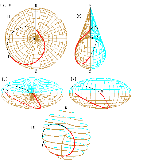
[1]: Cross-cap is right in front of us. The red curve is that of [1] in Fig. 7. But this Cross-cap is not flat, and so the red line turns at point t to the rear side smoothly.
[2]: It is the right side view. The sky blue part is the rear side of [1].
[3]: It is the bir's-eye view from the north pole (top) N. (The number of grid lines are reduced.)
[4]: It is the view from the south pole (bottom) S.
[5]: It is a slanting view. The curved line is like a circle. The greate circle on the hemisphere is not a circle but semi circle. But it forms a loop on Cross-cap as well as Mobius strip.
We will try to draw various curves on Cross-cap later in "Ch. 37: Cross-cap (3)". Here we see Cross-cap itself first.
**************************************************
They say that Cross-cap (projective plane) can be divided into Mobius strip and a disk. Let us see how they make it.
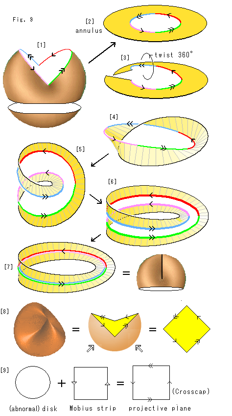 Look at Fig. 9.
[1]: We split Line of Self-intersection and open the upper part of Cross-cap. We color the edge of openig and put arrows to indicate how to identify Line of Self-intersection. And then we cut the lower part of Cross-cap as shown.
A diagram with this kind of arrows can be interpreted in two ways:
(a) It is regarded as that the identification has been done.
(b) It shows how to make identification without any action.
As far as we know, no book describes which is which, (a) or (b). But here we should distinguish (a) and (b). See [1] based on (b). We are going to make the identification of Line of Self-intersection.
[2]: We deform the upper part of Cross-cap to a disk with a hole. An object that can be regarded as a concentric circles is called an annulus. This [2] is an annulus.
[3]: We cut the annulus and twist it by 360.
[4]: The twisted annulus is rejoined.
[5]: We slenderly disentangle [4], and make a coil as shown.
[6]: It becomes Mobius strip with a cutoff portion along the center line.
[7]: Close the opened gap. Then we get Mobius strip. Line of Self-intersection (colored edge) is perfectly identified now. The red and pink edges are exactly glued, and so are the blue and green edges. This Mobius strip equals to the upper part of Cross-cap except their edges. The edge of Mobius strip is twisted but the skirt of the upper part of Cross-cap is not. What we say "equal" here means that they are in one-to-one correspondence. The symbol "=" is in this sense.
[8]: On the other hand, the whole of Cross-cap can also be expressed with a quadrangle that has arrows for identification. Split and open Cross-cap as shown. See it based on (a) mentioned in [1]. Push the bottom of Cross-cap upward, and press it down, then we get the quadrangle after a little deformation. We often see such a quadrangle with arrow in books on topology. The sides with the same arrow should be identified including their directions. We do not care about physical possibility of gluing for the identification. Here we should assume that the identification has been done abstractly.
[9]: It represents that Cross-cap is consists of a disk and Mobius strip. Cross-cap is a model of projective plane. The disk is the deformed lower part of Cross-cap [1]. Mobius strip is also expressed by a quadrangle with arrows. The plus sign means an abstract gluing.
An ordinary disk is OK if it is just for the lower part of Cross-cap. But this disk is to be glued to Mobius strip. That is, the edge of disk must fit the edge of Mobius strip. How can we joint what flattened (disk) and what twisted (Mobius strip)? It is absolutely impossible. So the disk is a quite abnormal matter. Let's finish it by saying "abstract".
In [7] how about the edge of Mobius strip and the skirt of the upper part of Cross-cap? The former is a coil which end points are connected and the latter is a simle loop. Nevertheless imagine that they are identical. Do not ask which equals to which. Say, it's an abstruct calculation.
The quadrangle on the right side of [9] has four arrows. It has double arrows  on the top and bottom edge where the quadrangle of Mobius strip has none. Not only the right and left edges but also the top and bottom edges are to be twisted.
It is impossible to glue the edges of quadrangle physically. But it is not true. It is possible if self-intersection is allowable. What glued becomes Cross-cap when we take it for granted that the self-intersection is natural necessary for gluing. Unfortunately, we have to regard Cross-cap as a plane. It is not too difficult to feel Cross-cap flat. Because all we have to do is to suppose that we live on Cross-cap. However, it is truely hard to draw a geometrical figure concretely on Cross-cap.
By the way, we feel uneasy about [3] where the annulus is cut. The annulus is two-sided, and so it can never be changed into Mobius strip whatever we fiddle around with it. So it must be cut. But it is very intentional, isn't it?
One more thing is weigh on our mind. The rest of Cross-cap after the disk is removed becomes Mobius strip. So we would like to say that an unhurt Cross-cap is Mobius strip. In order to do so we must treat the disk as an exceptional zone. The zone may be shrunk, and we may avoid it. But do not make the zone a point because a point and a disk are different. Fortunately we take off the disk anywhere excluding Line of Self-intersection.
Then let us use a convenient word "singularity" for the exceptional zone. So we can say that Cross-cap is equivalent to Mobius strip except the singularity, can't we?
Wait a minute. It is a talk without projective plane. Cross-cap covers the whole projective plane but Mobius strip does not. Therefore, as a result, the correct answer is that Mobius strip is a part of Cross-cap.
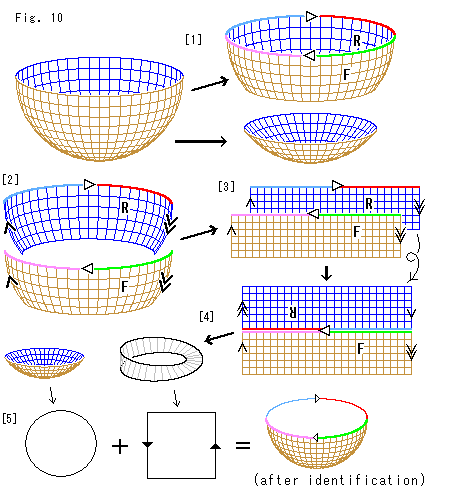
The abve talk about Fig. 9 was too quick for us even though it is correct. Let us begin with a hemisphere with identified antipodal points. It is projective plane, too.
Look at Fig. 10.
[1]: We carry out the identification of antipodal points. First we devide the hemisphere into two as shown. The upper is an annulus. We color its top edge and mark it with triangular arrows, and label F and R as shown.
[2]: Faces F and R are divided. We put arrows on their right and left edges as shown.
[3]: Flatten them into rectangles.
[4]: Turn R upside down without reversing, and glue it to F so that color edges are identified. The two left arrows together indicate upward and so downward the right arrows. So we twist and join the right and left, and make Mobius strip. Now the identification of the upper part of hemisphere is completed. (In previous chapters we cut rectangular strips out of hemispheres. Those rectangular strips are different from the rectangle here.)
[5]: We make the remaining of lower part a flat disk similarly to Fig. 10. And we express Mobius strip by a rectangle with arrows. The hemisphere after identification is projective plane, or Cross-cap. Now the picture formula shows that the disk and the hemisphere become the hemisphere when they are abstractly glued together.
The procedure for making Mobius strip from the hemisphere is quite different from that of Fig. 10. As a result, however, there is no difference at all.
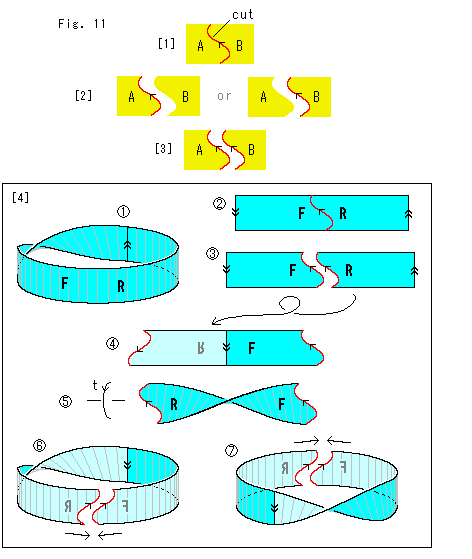 Look at Fig. 11.
To cut and rejoin a curved surfacelike is called surgery. It is a term in topology. Let us sort it out a little in our scope. (We do not handle such as so-called Klein's bottle that goes through itself.)
[1]: Suppose we cut the yellow surface into A and B along the red line.
[2]: If A has the end line (the red boundary line in [1]), B has no end line, and vice versa. This judgement is popularly used in mathematics. It is called Dedekind's cut. In daily life we cut a cloth into two, and find waste threads on both of cut clothes and some on the floor. But we never see any single piece of waste thread that clings both of the cut clothes at a time.
[3]: In topology, however, both A and B have their edges. Do not think that one became two. They are identical. In other words, we regard them as a single matter though they are separated. If it is agreeable, rejoining can be done quite naturally by identification. They say that both Dedekind's cut and this topologycal idea are postulates. What we say surgery is based on topology.
[4]: Let us give an example of surgery.
: It is Mobius strip. We mark letters F and R on the surface in our sight. Letters F and R are easy to see if they are turned or reversed. And we put the arrow  over ther.
: We cut Mobius strip at the arrow , and untwist and open it. And we get a rectangular strip with arrows and  on both ends. And we draw the red line in between F and R. Its shape doesn't matter.
: We cut the rectangular strip along the red line. What we "cut" is up to this point. Now we are going to make new identification (to rejoin).
: We reverse and turn upside down R, and rejoin arrows for identification. This strip at present is two sided, so we dull the color of reversed face.
: Fix the right end and twist the left end by 180 in the rotating direction t (clockwise viewed from the left).
 : Bend the right and left ends to toward us and round them. Well, we cann't make a new version. It will be exactly the same as the original Mobius strip if we identify the red lines together.
 : Then let's try to bend forward from us and round the both ends. Oh, it will become the original Mobius strip again. In fact our trial is just steps back to the beginning. In order to get a new surface we must twist the strip more, odd number of 180, or twist it reversely. Needless to say we would get a new version if we tangle the strip itself or with something else. However, whatever identification is performed, it dpends on the view point of the observer whether changed or unchanged.
Every suregry must be completed. Do not leave it on the way. The completion of surgery is done when all identification is finished. Any stage, however, can be regarded as the completion if we observe it after abstract identification. (A single cut is enough to get a new type of Mobius strip though we cut twice, Mobius stip and the rectangular strip . But it was just for the sake of explanation.)
What we should keep it in mind is that we reversed one of surfaces to be identified. The reverse is simply a local event. It is actually the same as a twist when we take a global view of it or see it after some more steps. The surface returns to be one-sided when identificatn is fully completed.
Moreover, it is important that all surfaces we can get by the above surgery are essentially the same. In other words, the character and function of a surface is unchaged whatever appears to our own eyes because we make full identification during surgery. Abstract identification is included, of course. Mobius strip never changes into a cylinder or like.
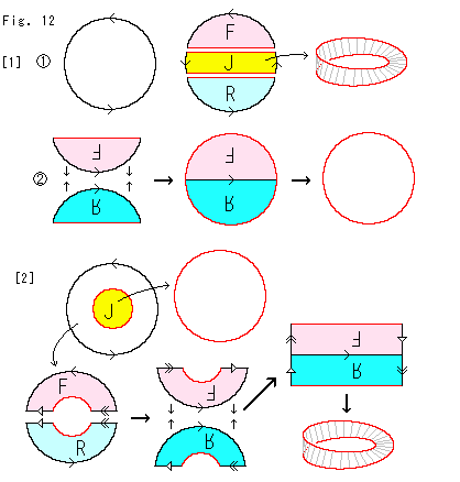
Look at Fig. 12.
Let us express projective plane by a disk and see the division of projective plane.
[1]: We cut the disk into three.
: The middle part J becomes Mobius strip.
: Turn F upside down without reversing the front and back. Turn R over and upside down. And glue F and R together as shown. Then we get the red disk.
[2]: Cut the circular yellow part out of the disk as shown. The yellow part becomes a disk as it is. It is an ordinary disk. The remaining annulus is cut into two, F and R. And we get Mobius strip via its rectangle.
Here we realise that the cutting procedures of [1] and [2] are completely different frem each other. Nevertheless, both results are exactly the same.
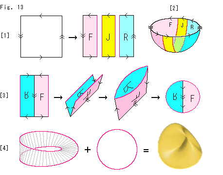 Look at Fig. 13.
Let us see the division of projective plane by using a rectangle with arrows. Here we carry out surgical operations mostly on the disk.
[1]: We cut the rectangle of projective plane into three, and label them F, J and R each.
[2]: It is a reference drawing. F, J and R correspod to those of the hemisphere.
[3]: First take F and R. Turn over R and join it to F. Fold and glue the upper and edges respectively. Then we get a boat-like surface. Now we can strech out it into a plane disk.
[4]: The remaining J becomes Mobius strip by gluing the upper and lower edges together after twist. The arrows on the diameter of disk can be omitted after identification. Now the picture formula expresses that Cross-cap consists of Mobius strip and the disk abstractly glued together. Pay attention to that their edges are commonly red just as before.
**************************************************
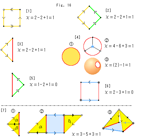
Let us see Euler number (Euler characteristic).
Here we list Euler number by surface.
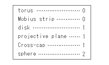
A disk is topologically the same as a sphere with a hole.
As seen in the table different surfaces have the same Euler number. We can not decide a surface whether twisted or not. To see it we have to examine arrows on edges of triangulation. Euler number, however, is realy powerful. It never change whatever a surface is deformed. Euler number is a topological invariant. Let's keep it in mind and go.
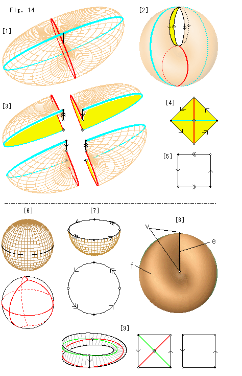 Look at Fig. 14.
First we seek Euler number for Cross-cap.
[1]: We triangulate Cross-cap. The black line is Line of Self-intersection. The sky blue line goes along the ridge-valley line and the red line intersects orthogonally to the sky blue line. Its bottom point in common with that of the sky blue line but the top point ends to the bottom end point of Line of Self-intersection. For the sake of simplicity we use these lines as edges of triangles.
[2]: We split Line of Self-intersection so that it exposes four segments to be identified. Their upper ends form a common point, and so do the lower ends.
[3]: Four triangles are separated. In this case all of them are so distorted that every internal angle is right angled.
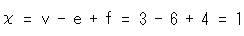
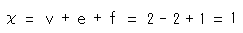
[4]: We stretch and flatten triangles, and glue common lines, red to red and sky blue to sky blue together as shown. Now we can accurately count the number of vertices v, edges e and faces f after identification, namely, v = 3, e = 6 and f = 4. Then Euler number  is
is
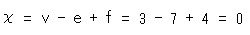
 [5]: The diamond [4] becomes a standard rectangle of projective plane with identical vertices if we eliminate the central vertex and interior four edges. We can also get Euler number of this rectangle. We regard the vertices as those of triangulation, and count v, e and f. The each numer of them are reduced from [4] but we get
 Euler number is unchanged.
Here we should pay attention. The point at each corner of the rectangle on the drawing is not a common point of three segments like a vertex of triangulation. But it will be a vertex of triangulation when we make Cross-cap with the rectangle.
Luckily, in many cases, it is useful to treat vertices of the rectangle as vertices of triangulation. We go on without question. Let us think about it when we find anything irrational.
[6]: It is quite easy to find that Euler number of Cross-cap is 1. It is well known that Euler number of an ordinary sphere is 2. We use that fact. A sphere with identical antipodal points is a model of projective plane. The numbers of v, e and f of the sphere are exactly the half of those of an ordinary sphere. Therefore, Euler number of projective plane is a half of 2, or 1.
If the inside of sphere is not empty, it shall be a model of projective space but we are interested in only surface now.
[7]: We cut off the half of sphere with identical antipodal points, and get a hemisphere. The Euler number of the hemisphere remains unchanged. Because every point on the hemisphere excluding its edge (the equator) has no partner to be identified, and so the numbers of v, e and f do not change. Therefore, the Euler number of the hemisphere is 1. And the Euler number of Cross-cap made of the hemisphere is 1, too.
Also we can directly get Euler number of the hemisphere. Let us see it from above and compare it with the rectangle [5]. They are topologically the same. And we get Euler number as well.
[8]: We have no need to take the trouble to traiangulate Cross-cap for its Euler number. We can count the numbers of them as 2v, 2e and 1f as shown, and immediately we can say Euler number equals 1 similarly to [5].
[9]: How about Euler number of Mobius strip?
Since v = 3, e = 7 and f = 4 by triangulation,
 If we eliminate one vertex and four edges from the rectangle (rectangular strip) similarly to [5],
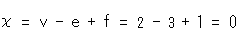 We could get Euler number of Mobius strip from its rectangle with arrows, too.
Mobius strip is of course not projective plane because its Euler number is zero. (It is said that a surface with zero Euler number admits Eucliean geometry. We, however, won't get involved with it.)
We are going to see more about Euler number, but in advance let us see another dividing way of the rectangle of Cross-cap (projective plane).
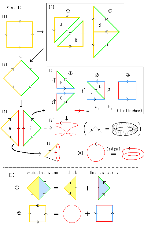 Look at Fig. 15.
[1]: It is the standard rectangle with arrows that represents projective plane.
[2]: We change the rectangle into a new one which is convenient for us to handle.
: We cut the rectangle along its diagonal into two parts, J and R. And we put triangular arrows on new green edges.
: Turn over R and glue edges with arrow together for identification.
[3]: We get the new rectangle shown as a rhombus. The line with arrow is omitted since its identification has been done. We wish this rectangle would be drawn. But it is impossible even with self-intersection.
This new rectangle is essentially the same as the original [1] because the box [2] is just for redrawing. So we can use [3] instead of [1], and we can directly come down to [3] from [1]. The dotted arrow shows it.
Now we start with this rectangle.
[4]: We cut the new rectangle along its diagonal into two parts, triangles A and B. And we put arrows on the new red edges.
[5]: Let's take triangle B first. We change it into the rectangle of Mobius strip.
: Triangle B is cut into triangles F and G. We put arrows on the new blue edges. The red lines of F and G are accompanied by the arrows f and g respectively. We do not put an arrow on any red line. Because the red lines of F and G are not to be identified. They are different parts of the red line of triangle B.
: Turn over G and glue green edges together for identification of them.
: It becomes the rectangle of Mobius strip omitting the green diagonal. The arrows f and g are eliminated because the red lines are automatically connected in seies when the blue edges are identified.
[6]: It is Mobius strip obtained from [5]. Its red line is a single loop that is a series connectives of two red edges of the rectangle of Mobius strip.
Box [5] is an operation on the way from triangle B to Mobius strip [6]. The blue line appeared only in that operation. So we can skip box [5] entirely. The dotted arrow shows it. That is, triangle B may directly change to Mobius strip as shown in the parentheses.
[7]: The remaining triangle A is easy to identify its yellow edges, and it becomes a cone-like. We push down the vertex of cone to the base and get the disk.
[8]: Thus we realised that edges of the disk and Mobius strip are identical.
[9]: Let us express the division of projective plane with triangles and rectangles with arrows.
: It is drawn by using [3] and [4]. It is valid as surfaces and so we colored inside of every figure. These triangles are abstract but we can freely divide and link them without deformation.
: The standard rectangle [1] is divided into the disk and the rectangle of Mobius strip. There is no common color between the left side and the right. Every figure is naturally a surface but we can not paint its inside like . The disk is an ordinary one. And the edge of Mobius strip is the upper and lower red lines of the rectangle. Gluing edges together without contact of surfaces is impossible. We now realise that and should be complementary to each other.
Now let go back to Euler number.
How is the procedure of the divisin and union related with Euler number? We see it with rectangles and so forth.
 Look at Fig. 16.
End points of edges are treated as vertices of triangulation. But they are not marked after the triangulation. We mark vertices depending on arrows. And we count vertices with the same mark as one, edges with the same arrow as one. We include some figures and expressions drawn before. Go and see the following while comparing it with Fig. 15.
Euler number does not change with twist. We can judge a twist by arrows on edges.
[1]: It is a standard rectangle of projective plane (Cross-cap).
[2]: Rectangle [1] is a deformed by surgery. One vertex  is added and one vertex
  is eliminated.
[3]: It is the left half of [2].
[4]: Triangle [3] is deformed into a disk.
: If we count the numbers of vertices v, edges e and faces f of the disk as it is, Euler number we get becomes 0 - 1 + 1 = 0. Zero Euler number is no good because Euler number never change by deformation.
As for triagulation,
each surface must be topologically a disk,
and each edge must be topologically a line segment.
: The circumference of disk is not a line segment. So we count vertices v, edges e after proper triangulation.
: A disk is topologically the same as a sphere with a hole. It is a sphere that lacks one faces in triangulation. Therefore, Euler number for the disk is Euler number for an ordinary sphere minus 1, or 2 - 1. The result is the same as , of course.
[5]: It is the right half of [2].
[6]: It is Mobius strip made of [5].
[7]: Let us try to join [3] and [6].
: We divide triangle [3] into  and
and  .
.
: and are glued to the right and left sides of [6] as shown. Triangle is reversed.
: It is a pyramid that lacks two faces. We identified only vertices . We want to idenfify all of vertices and edges but we can not continue no more.
It is natural and well known that a disk is toporogically the same as a one-holed sphere. We found it useful in the above. Also the pyramid appeared. These facts suggest us something, don't they?
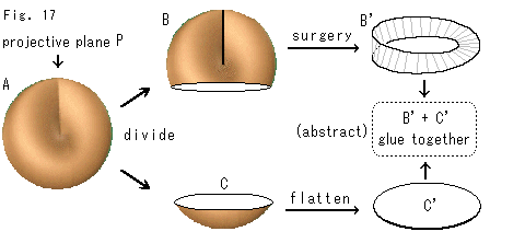 Look at Fig. 17.
It is said that the true character of projective plane is a Mobius strip covered with a disk or a one-holed sphere with Mobius strip that fills the hole. These wording are not much smart for us.
Cross-cap A that is projective plane P is divided into B and C. B changes to Mobius strip B' by surgery. C changes to a flat disk C'. Now they say B' + C' is the true character of projective plane. It is funny, isn't it? What they say is that P = B' + C' even after B and C changed into B' and C' because P (= A) = B' + C'.
Let us supplement it.
"abstractly" does not mean to go back to the origin, of course. "abstractly" here is to imagine by force that P = B' + C'.
The disk C' is certainly an ordinary disk. But it is while the disk is alone. We should guess that the disk behaves itself mysteriously for gluing to Mobius strip.
As to disassemble projective plane into Mobius strip and a disk, we will try it more in different ways. So please read some more chapters (up to Ch. 37). Then you shall feel it natural.
[Back] [Next] [Contents]