
Ch. 41 Crosscap (3) 
We will make a new Cross-cap with numberless Mobius strips taken out of projective plane. Cross-cap or projective plane can be divided into Mobius strip and a disk. It will be easier for us to observe relations among them with this new Cross-cap.
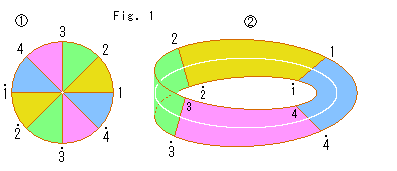 Look at Fig. 1.
A disk and Mobius strip are exchangeable as previously constructed. Let us see which part of the disk corresponds to which part of Mobius strip.
 : We divide the disk into 8 equally by 4 diameters and color it as shown. The center, however, can not be divided by coloring. The end points of every diameter are numbered.
 : Disk
  became Mobius strip. The center of the disk is a single point, and now it is the center line of Mobius strip. Every colored area corresponds to that of the disk except the center of disk. One to one correspondence stands up in the colored area.
We will think about the center line by and by.
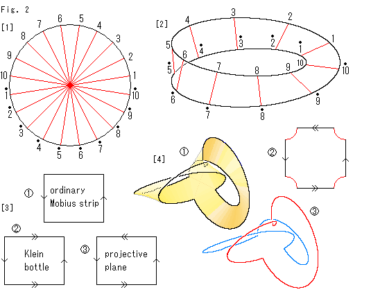 Look at Fig. 2.
[1]: It is a disk with identified antipodal points, namely projective plane in circular shape. Let us call it Disk-type projctive plane.
[2]: According to previous pages, we can number the edge of Mobius strip as shown. The number corresponds to that of Disk-type projctive plane. However, Mobius strip with identified opposite points on the edge is not projective plane. It is what is called Klein bottle that has neither inside nor outside.
[3]: In rectangle we can show an ordinary Mobius strip, Klein bottle and projective plane as  ,
,  and
and  respectively.
[4]: It is easy to work, if partially, Mobius strip into projective plane. All we have to do is to joint two Mobius strips crosswise like  . This picture was drawn before. But at that time, we simply aimed to widen Mobius strip. Our current idea is different from it a little. First there is Mobius strip with points on the edge to be identified, to be twisted and joined. The picture here is what the identification has partially been done.
It is impossible to glue the black edge of the crossed mobius strip  .
Instead, let us imitate a square with arrows. It would be a square
  with truncated corners. A red line at any corner can not be glued to any part of the square.
The edge of an ordinary Mobius strip is a single loop, but the edge of crossed Mobius strip can be colored in two as shown  .
.
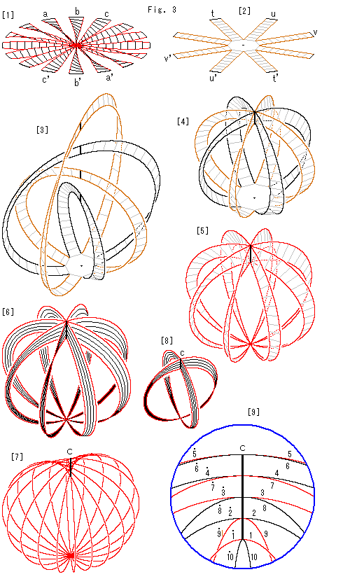 Look at Fig. 3.
Now we make a new Cross-cap with Disk-type projctive plane.
[1]: Disk-type projctive plane is a circle. We do not mentally identify its antipodal points as it is . But we put it in action physically.
The disk is cut in fanwise, and its fins are twisted. We want to glue each pair of antipodal edges, a to a', b to b', c to c', and so on. Well, it is not easy to draw it immediately.
[2]: For the present, we cut the disk in another way, not propellerlike. Rectangular strips are arranged around the octagon that surrounds the center of disk. Since it is a detour construction, edges of rectangular strips are not colored red.
[3]: We join every pair of antipodal edges after twist. The twisting directions are made evenly. The black bridge on each thin strip is the joint line. Thin strips look like octopus legs, doesn't it? They are Mobius strips. Colors of the legs are changed alternately for easy observation.
[4]: We deside that black joint lines are free to pass through, and we let Mobius strips intersect each other as shown.
[5]: The octagon is shrunk to a single point. It is what the identification of antipodal points of [1] is done. The edges are colored red in order to show that they are diameters of Disk-type projctive plane.
[6]: We split Mobius strips thinly and thinly. We assume that they become the diameters.
[7]: It looks like an apple. So call it Apple. The Apple is made of the diameters. The joints of Mobius strips is the segment c now. It shall be Line of Self-intersection, we guess.
[8]: The joint points on the segment c must be arranged to form Line of Self-intersection.
When we saw [1], we thought that the number of mobius srips is the more the better. But the appropriate number of them is two. It is understandable if we recall how we made Cross-cap from a hemisphere. We can also use the cross-shaped Mobius strip in Fig. 2 after looping one side, not back to back. Let us use this [8] instead of [6], and make Apple[7].
[9]: It is an enlargement of the segment c with diameters. The lines are numbered according to Disk-type projctive plane of Fig. 2. For easy observation, lines with even number are black and lines with odd numbe are red. Now we see a pair of lines of the same nmber with and without a dot are certainly jointed. Moreover, they are in right order for Line of Self-intersection.
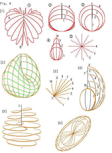 Look at Fig. 4.
Let us construct a Cross-cap, or Apple.
[1]: The surface of Apple is kind of an ellipsoidal surface of revolution. The axis of rotation is the extended line of segment c. When an ellipse turns while its radius on the axis of revolution change, it forms Apple.
 : It is Apple, not a skeleton, tilted to us. A is the largest ellipse and B is the smallest ellipse. The black segment c is the pivot. Its length is enlarged for easy to see.
 : We prepare many ellipses 1, 2, 3, , , to make
  . Their horizontal axes are constant but vertical axes are variety. We put them in order as shown.
 : Fix the largest ellipse 4 (A of
  ) and turn the smallest ellipse by 90
 . Then arrange remaning ellipse inbetween them. The figure shows turned ellipses. It is equivalent to Apple
  .
.
 : It is the side view of
  .
.
 : It is the bird's-eye view of
[2]: If we use countless ellipses, we can get a beautiful Cross-cap. Its three-D proportion is somewhat modified for a look. The brown lines are edges of ellipses in regular intervals of turning angle. The green lines are traces of the central angle of ellipses. The shape of every green line is like the edge of a saddle. They are in regular intervals of the central angle. Let us regard the brown lines as the longitude (meridian) and the green lines the latitude.
[3]: We cut the Cross-cap into right and left parts. The diagram shows the bird's-eye view of ellipses in the right. We newly number them.
[4]: It is the skeleton of right part of [2]. The green lines are omitted. Line numbers are those of [3]. We can see an ellipse is turning as changing its vertical size.
[5]: We horizontally slice Cross-cap [2]. The figure eight parts appeared. That is to say, [2] is certainly a Cross-cap. The edge of Disk-type projctive plane is the segment c that is the line of self-intersection now.
[6]: It is the bird's-eye view of [5]. In [5] it might look twisted vertically a bit, but not really.
 Thus we could make a new Cross-cap. But it looks none the better for the change. Nevertheless, it was not done by imitating the shape only. Therefore, we can say that the new Cross-cap is made automatically from the Disk-type projctive plane.
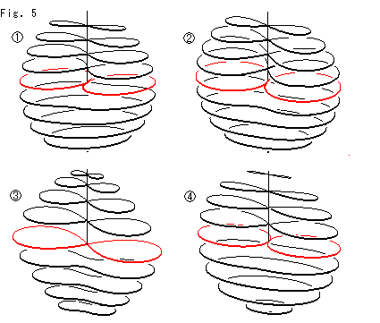
Look at Fig. 5.
Let us line previous Cross-caps up together with the new Cross-cap. They are skeletons with horizontal slices. Each Cross-cap has the red line that passes the bottom end point of Line of Self-intersection.  is our new Cross-cap.
  is made of a hemisphere,
  is made by applying Cassinian oval. And
  is of a non-hole torus. They are essentially the same.
But the new Cross-cap is quite convenient. Because it is easy for us to describe a point on Cross-cap. Moreover it is quite easy to understand the relations to Disk-type projctive plane. (Some books show several mathematical expressions of Cross-cap. But, as far as we are concerned, none of them is useful even for darawing an appearance.)
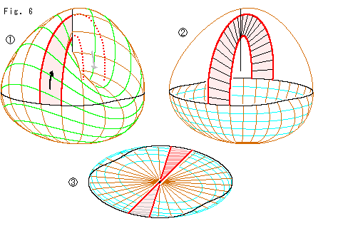
Look at Fig. 6.
Let us follow the red belt on Cross-cap to the other side through Line of Self-intersection as shown in  . We eliminate the upper part above the black line of Cross-cap to see the belt as
  . It looks like a hand basket, isn't it? The handle appears only its one side. But it is twisted. See it carefully.
  is the bird's-eye view of
  . The handle is apparently twisted.
We previously observed the figure-eight cut  of Cross-cap. Now more vividly we see that Cross-cao has the same character as that of Mobius strip. Compare the hand basket
  with [5] in Fig. 3.
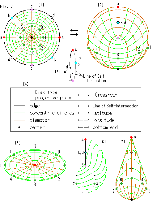 Look at Fig. 7.
Now let us see how Cross-cap corresponds to the Disk-type projctive plane. Here we use terms "longitude" and "latitude" for our convenience. We guess that any two curved surfaces can be corresponded each other if we set longitude and latitude with the origin. Corresponding points here are shown with big color spots.
[1]: It is the Disk-type projctive plane. 10 brown diameters are drawn. The concentric circles consist of 10 circles including the black edge. Each pair of antipodal points on the edge are the same color. The green are distingushed by number. The black spot is the center.
[2]: It is Cross-cap. It stands straight up with the minimum ellipse perpendicular to the screen.
Brown longitude lines and green latitude lines correspond to diameters and concentric circles of Disk-type projctive plane respectively. The number of green lines on Cross-cap may look reduced but it is unchanged. Green spots 6, 7 and 8 are on the rear side.
The black Line of Self-intersection correspons to the circumference of Disk-type projctive plane. Points b and d are doubly drawn but they are different. Points on the edge of Disk-type projctive plane are antipodal points. Therefore, the actual number of points on the edge is half of that drawn. Namely points on Disk-type projctive plane and Cross-cap are one to one correspondence.
[3]: To see situation of points b and d we split Line of Self-intersection by force as shown with arrows. Points a, b, c and d are singles after identification.
In the diagram the red spots at right and left ends of Disk-type projctive plane are transferred onto the top of Line of Self-intersection. But we can choose other antipodal points for the top. If we do so, points on Cross-cap move accordingly. That's all.
[4]: It is the chart of correspondence between Disk-type projctive plane and Cross-cap.
[5]: It is the bird's-eye view of transparent Cross-cap. It is not that of [6] in Fig. 4, which was a contour line map. Green lines in this diagram are lines of latitude of Cross-cap [2]. The latitude lines are actually in saddle shape but their top view is like this [5].
[6]: We cut Cross-cap [2] along Line of Self-intersection perpendicularly to the screen. The diagram is the oblique view of right half of it with latitude lines only. The black points are end points of cut latitude lines on the cross section.
[7]: It is the left side view of Cross-cap [2]. Line of Self-intersection is hidden but we can see its top point a. Other points b, c and d on Line of Self-intersection are drawn in dotted circles.
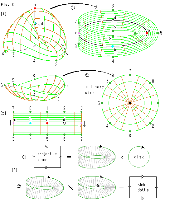 Look at Fig. 8.
We have observed several facts that projective plane consists of Mobius strip and a disk. Let us think it over again since we found concrete crespondesnce between them.
[1]: We cut Cross-cap into two, the upper and the lower.
 : We suppose that the center line of Mobius strip can be corresponded to Line of Self-intersection of Cross-cap. The center line is a single loop, so it is convenient. See [3] of Fig. 7. Then we arrange other points accordingly.
This black center line effects nothing but show its location only. Points b and d are exchangeable while others as they are.
Mobius strip here is not made of Cross-cap by surgery and deformation like we have done before. Way of thinking is different though the result is the same.
 : The lower part is flatten as an ordinary disk.
[2]: It is a rectangular strip made by cutting Mobius strip.
[3]: Now, we glue the disk to Mobius strip. It is impossible to glue all of green spots at a time.
We have felt that a word "glue" is a verb. That forced us to imagine this way and that. Here we are free from such a force. We do not move neither Cross-cap nor Mobius strip. We make neither cutting nor gluing. We simply judge that a point corresponds to another point, they are the same. Picture  shows it. Sign "*" does not mean gluing but correspondence of points on edges. The black arrow shows lines (not faces) to be identified by point to point correspondence. Note: the edge of Mobius strip must not be identified its opposite edge. If it is done, Mobius strip changes into a Klein bottle. Picture
  is a description of it.
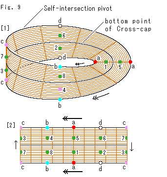
Look at Fig. 9.
Nothing venture, nothing win. We chose the origin (the bottom of Cross-cap) as the center of disk. How about the center line of Mobius strip for the origin? It is not a point but a line. But let us use it as the origin. And we forget about the disk.
[1]: The center line of brown Mobius strip corresponds to the bottom of Cross-cap. It is of course not one to one correspondence, we know. The edge corresponds to Line of Self-intersection. Then we can set all other points on Cross-cap onto Mobius strip as shown.
The diagram shows that we can make point to point correspondence between Cross-cap and Mobius strip, with a single exception of the origin.
However, points on Line of Self-intersection have not idenified yet. So we add arrows. That is to say, this Mobius strip is a Klein bottle, and not projective plane. It is true but we might be able to use it for something. So let us call it MK-type projective plane for convenience.
[2]: It is a rectangular strip made of [1]. It has arrows on the upper and lower edges.
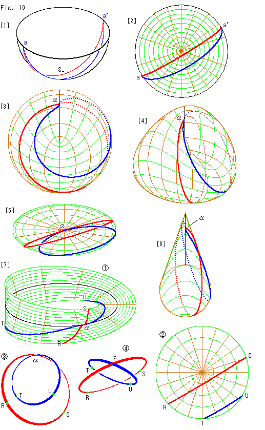
Look at Fig. 10.
Since we found point to point correspondens between Cross-cap and other projective plane, let us draw some curved lines. Starting with parallel lines.
[1]: The red and blue lines aa' are pararell lines on the hemisphere which antipodal points are identified. Point S is the south pole.
[2]: It is Disk-type projctive plane. Parallel lines on it is the top view of [1]. Suppose we travel from point a to a'. We reappear at point a the moment we arrive at a'. And there is no end, a - a'- a - a' --- .
[3]: It is paralle lines on Cross-cap. Visual end points a and a' are jointed at point  on Line of Self-intersection. The dotted lines are on the back.
[4]: It is the oblique view of [3].
[5]: It is the top view of [3].
[6]: It is the side view of [3].
[7]: Now let us divide projective plane (Cross-cap, Disk-type projctive plane) to Mobius strip and a disk.
On the separated Mobius strip  we can clearly recognize that the red line and blue line of parallel lines cross each other at point
  on the central line that was Line of Self-intersection of Cross-cap.
On this Mobius strip if we travel from points R, T to points S, U, we automatically jump to points S, U on the disk  from the same points on Mobius strip, and we can continue to travel. When we arrive at points R, T on the disk, we jump back to points R, T on Mobius strip, automatically again. And we can go on endlessly.
Here we are aware of that the routes of the red and blue lines on the disk are not exchanged after traveling on Mobius strip where they make intersection each other surely. Isn't it strange? But it is evidence that projective plane is different from Euclidean plane.
It is physically impossible to glue a disk to Mobius strip. So we take out only the parallel lines after joint.  shows them.
  is a view turnd point
  to us. They are the parallel lines on Cross-cap.
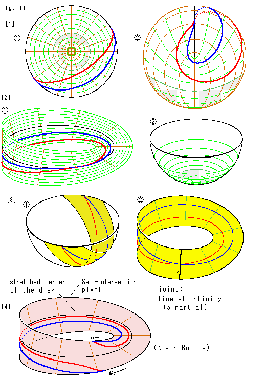 Look at Fig. 11.
A line we draw also divides when we divide Cross-cap into Mobius strip and a disk. But there is a way to avoid it. We can use a small disk that no line passes. But it is no use if the disk center is on a line. So let us make it an exception.
[1]:  is Disk-type projctive plane with the red and blue parellel lines. The gray part is the corresponding domain of the disk. As you see, the parellel lines do not pass through the gray area.
  is Cross-cap with the parallel lines transferred from
  . The gray part also corresponds to the disk edge.
[2]: The parallel lines are transferred onto Mobius strip. This Mobius strip  is what is left after removing the disk from Disk-type projctive plane or Cross-cap.
  shows the location of disk in hemisphere. We can also get Mobius strip
  after identifying antipodal points on the edge of hemisphere without the disk.
This Mobius strip is not the entire projective plane, but we can see the whole of parallel lines on it. In many cases we do not need the disk. Therefore, let us call the Mobius strip Mobius-type projective plane and put it to practical use.
[3]: We previously made a Mobius strip from a hemisphere. We could see the whole of parallel lines on it if they did not run out of edge. It was made by cutting the hemisphere like  . What is the differences btween this Mobius strip
  and Mobius-type projective plane? Let us see it.
The center line of Mobius-type projective plane corresponds to Line of Self-intersection, that was the entire edge of hemisphere. And the edge is a line at infinity. In short, the center line of Mobius-type projective plane is a line at infinity. The joint of the yellow Mobius strip was the edge of hemisphere that is the line at infinity. But it is only a part of line at infinity. It is a great advantage that Mobius-type projective plane has the whole of line at infinity.
The direction of joint of Yellow Mobius strip is different from that of the central line of Mobius-type projective plane. The difference is almost a right angle. And green segments crossing the belt do not corresspond to the diameters of Disk-type projctive plane but to the latitude lines. In another words, the directions in the length and breadth of these two Mobius strips are exchanged, not overall though.
[4]: Let us use another Mobius strip for a trial. It is MK-type projctive plane. It is not an ordinary Mobius strip and so its ground color is different from others. The parallel lines transferred from the above appears as shown. Antipodal points on the edge that is Line of Self-intersection are not identified yet. As a picture, the behavior of parallel lines look like the reverse of that of the green Mobius strip in [2]. But it is not true. The edge of Mobius strip [2] is not the stretched center of the divided disk.
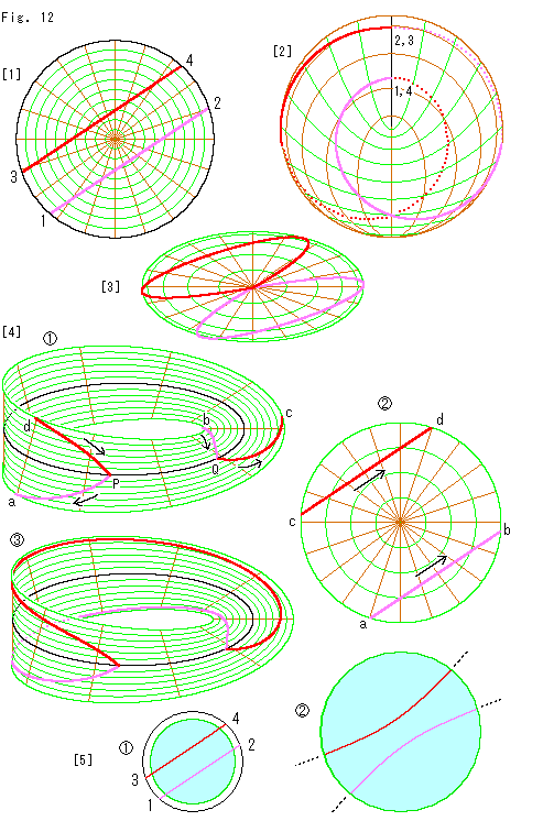
Look at Fig. 12.
[1]: We draw a single line that looks straight visually on Disk-type projctive plane. It circulates 1 - 2 - 3 - 4 - 1 - 2 - - -. To see it clearly the line is painted in two colors, red and pink.
[2]: It is the line on Cross-cap. The dotted parts are on the back.
[3]: It is the bird's-eye view of [2]. The line endlessly extends while drawing the constant figure-eight.
[4]:  and
and  are Mobius strip and the disk that are separated parts of projctive plane.
  is Disk-type projctive plane. The red-pink curve on them are transferred from [1].
Let us take a look at  and
and  . Suppose we start from point P on the central line (Line of Self-intersection) to point a on the edge. Then the course we travel is:
P - a - (a - b) - b - Q - c - (c - d) - d - P - - -
It goes on and on while jumping between  and
and  . Points in brackets "()" are on the disk.
On Disk-type projctive plane, the curved line is a single loop.
The red-pink line cuts the center line at two points P and Q. It is because that a visual straight line is not a real straight line in projective plane.
It is agreeable, but the curve acutely folds there, doesn't it? Because the curve actually folds when we pass points 1(=4) and 2(=3) on Disk-type projctive plane. As we saw Fig. 10 or Fig. 11, if the line curves as a projected great circle on the sphere, it smoothly pass a single point on the center line.
[5]: Then, what kind of Euclidean curve that looks strait on Disk-type projctive plane?  is a shrunk disk of [1].
  is Euclidean disk that corresponds to the sky-blue area in
  . We can not draw Euclidean disk with infinite radius. So the sky-blue area in
  is limited as shown. The single line in Disk-type projctive plane appears in the Euclidean disk as expected. It looks two innerly curved lines that is a pair of hyperbolas.
(We want to do a similar thing to this picture. But it is impossible, we know. Nevertheless, we will device in time.)
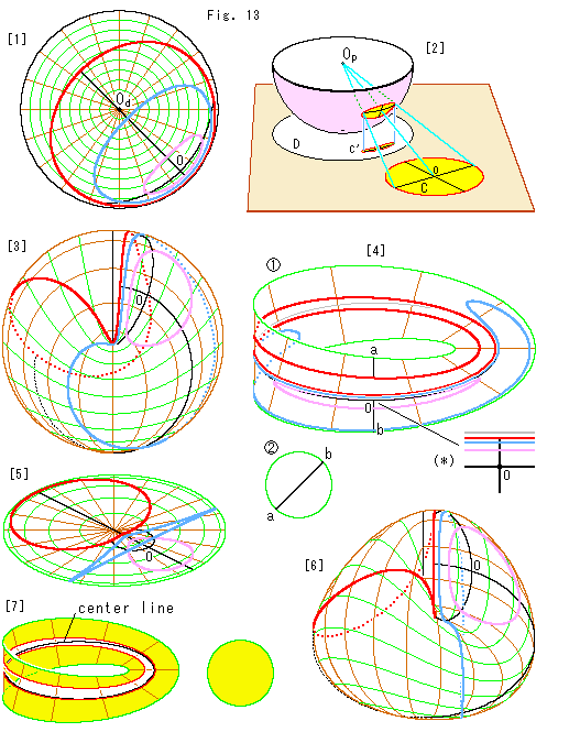 Look at Fig. 13.
How about a circle?
[1]: The three loops are concetric circles on Disk-type projctive plane. The two black lines are orthogonal diameters of the concetric circles, one of which passes the center  .
.
[2]: It shows how we get a circle on Disk-type projctive plane. The white circle D is Disk-type projctive plane. The red framed circle C is a Euclidean circle. They are on the brown plane. We transfer circle C into circle D via the pink hemisphere as shown. Point  is the center of hemisphere. The circle C is projected to the sphere by central projection with its center
  , and then perpendicularly drapped onto circle D as circle C'.
This is the reason why the concetric circles on Disk-type projctive plane look distorted.
We immediately understand that circle C' never touch the edge of circle D whatever the circle C is enlarged. In a particular case that circle C is unlimitedly enlarged, circle C' becomes the circumference of circle D. In all cases, however, circle C' never cut circle D.
[3]: The concetric circles are on Cross-cap now. Dotted lines are on the back. It is certain that none of the three curves cuts Line of Self-intersection. It is true, but it is not easy for us to see three curves in this diagarm are in the form of the concetric circles, isn't it?
[4]: Cross-cap [3] is divided into Mobius strip  and a disk
  with the concentric circles. We let the disk so small that all of three circles are on Mobius strip. Latitude lines are omitted for easy observation. The gray line is the center line that corresponds to Line of Self-intersection of Cross cap. The right below (*) is an enlargement around the center O.
On Mobius strip  the red circle makes double circuits, because it surrounds the center
  of Disk-type projctive plane. The diameter that passes the center
  transfers to the disk
  at points a and b.
None of circles cuts the center line because the whole concentric circles are kept inside of Disk-type projctive plane. Remember the corresponding relations:
 By the way, see Mobius strip with the magnified picture (*). We find that the center point O of concetric circles is outside of the red loop. How come?
[5]: It is the bird's-eye view of [3]. The center point O is outside of the blue loop, too.
[6]: We turned Cross-cap [3]. Now we can observe the layout of the three curves more easily. They are on 3-D surface, not on a single plane. That is why they look such as [4] or [5].
[7]: The center point of a circle must be inside of the circle. So we painted the inside with attention paid to the location of center. Now we understand that the center line side is the outside of red circle.
The center line corresponds to line at infinity. Therefore, we can regard the center line side as infinite space. And also we realize that our common sense "the outside is wider than the inside" is valid!
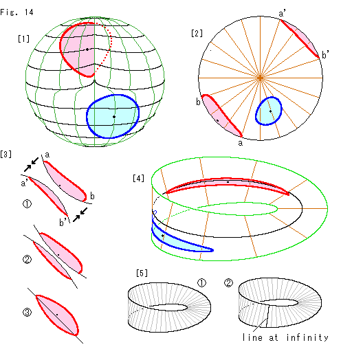 Look at Fig. 14.
Any circle on Cross-cap transferred from the disk-type projective plane never goes across Line of Self-intersection. Now then, what will happen if we draw a curved line that looks like a circle on Cross-cap and cuts its Line of Self-intersection?
[1]: The red and blue curved lines are drawn as visual circles on Cross-cap. They simply imitate an ordinary circle. Their diameters are given by straight distance regardless unevenness. That is why the red curve is somewhat distorted. The red dotted line is on the back. (This Cross-cap stands almost upright. Its lattice is only to show the dent clearly.)
[2]: The red and blue curves are tranferred onto the disk-type projective plane. The red one looks divided into two parts. But it is not true because antipodal points are identified.
[3]: We have to see the red curve on the disk-type projective plane with an imagination. Let us take the lower left for example. Turn it over and put it with the upper right like  . Let them get close each other as shown arrows without making intersection of black circular arcs.
  is on the way. Finally they stick to each other as
  . Well, it looks like a rugby ball. It is because that the closer we go to the disk edge, the thicker the density of space gets.
When we imagine like  ,
,  or
or  as they are on projective plane, we must remember that the black line is a line at infinity. Namely a figure that touches the circumference of the disk-type projective plane is expanded infinitely. A disk with antipodal points simply identified and the disk-type projective plane are essensially different.
[4]: The red and blue curve are on Mobius-type projective plane now. Fortunately none of them is divided. They are closed curves perfectly though they do not appear like circles. The black center line is equivalent to the circumference of the disk-type projective plane. The area on and around the center line is so expanded in reality.
[5]:  is an ordiary Mobius strip. If we draw a line at infinity on it as
  , the situation changes suddenly and completely. However, it is always one-sided.
Similarly, remember that Self-intersecton pivot of Cross-cap is the line at infinity. It is right but we often treat it as a Euclidean object. We had drawn Mobius strip with a line at infinity and showed a ball that bcame smaller and smaller to the line at infinity. But we have not drawn such a ball on Cross-cap. The reason for it is that we can not clearly show the situation around the line at infinity. Also, we usually get right result with Euclidean drawings.
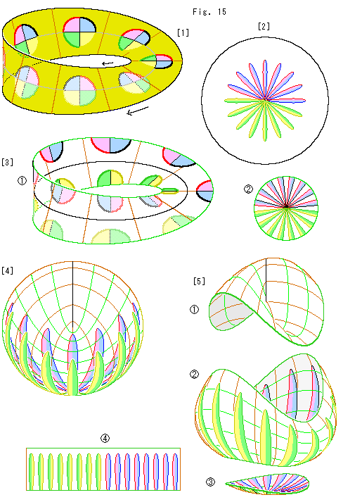
Look at Fig. 15.
We lay visual circles on MK-type projective plane. And let us see what happens.
[1]: This Mobius strip with arrows is a Klein bottle and so we colored dull. Every circle is drawn with an ordinary compasses and its center is on the center line. To see which is which part circles are painted four colors. Fainted ones are rea side of circles. Mobius strip is one-sided, but not partially.
[2]: The circles are transferred onto the disk-type projective plane. They look like a chrysanthemum. They are twisted 180 from MK-type projective plane [1] and tightly bundled at the disk center. It is natural because the center line of [1] is the stretched point of bottom of Cross-cap (the center of disk-type projective plane).
[3]: The disk-type projective plane is divided into Mobius-type projective plane  and a disk
  . This disk is the same as a central part of the disk-type projective plane. The remaining parts of circles appear on Mobius strip
  as shown. Parts of circles on Mobius-type projective plane
  do not look to fit wedge-shaped parts on the disk
  . But they will smoothly meet each other if edges of
  and
and  are abstractly glued.
[4]: It is a view of transparent Cross-cap with circles.
[5]: We divide the Cross-cap into three parts  ,
,  and
and  . The top
  includes Line of Self-intersection. Remaining parts can never be a Mobius strip whatever cutting.
  is the same as a cylinder. So we can simply cut and open it as a rectangular strip. And
  will be a disk of [3] by press.
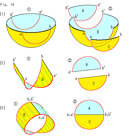
Look at Fig. 16.
There are two ways to get Mobius strip from a hemisphere. We referred to it a little at [3] of Fig. 11. Of course, there is no essential difference between them. But our way here is quite easy to see that projective plane consists of Mobius strip and a disk.
[1]:  is a hemisphere that we are going to identify antipodal points on the edge. We cut it along the red lines as shown. And we separate it into A, B and C as shown in
  .
.
[2]: The middle part B is twisted by 180 . Either left-handed or right-handed will do. The end parts A and C are flattened.
[3]: We joint the black edges of B and get Mobius strip. Also we join the black edges of A and C, and get a disk.
Mobius strip  is colored in two, but it shall certainly be single color if we paint it now. The disk should also be single color.
We previously applied this method with a square with arrows. Here we should pay attention to that the edge of hemisphere that is equivalent of Line of Self-intersection of Cross-cap is divided into Mobius strip and the disk. And it traverses Mobius strip.
Needless to say, Line of Self-intersection is line at infinity. Therefore, we can use this Mobius strip as a projective plane unless the whole of Line of Self-intersection is needed. But correspondence in Fig. 7 is not applicable.
[Back] [Next] [Contents]
 Look at Fig. 1.
 Look at Fig. 2.
 Look at Fig. 3.
 Look at Fig. 4.
 Thus we could make a new Cross-cap. But it looks none the better for the change. Nevertheless, it was not done by imitating the shape only. Therefore, we can say that the new Cross-cap is made automatically from the Disk-type projctive plane.
 Look at Fig. 7.
 Look at Fig. 8.

 Look at Fig. 11.
 Look at Fig. 13.
 Look at Fig. 14.
