We have met various models this and that. Let us see their mutual relations in series. However, we can not expect to peep the reality of hyperbolic space like when we made a pseudosphere from upper half-plane. Say, we see everything, wandering from one model to others. That's a part of our routine.
By using projection rays, we can see connections among five kinds of models in series. They are the hyperboloid, Poincare disk, Klein disk, the upper half-plane and the hemisphere. First we see relations between the hyperboloid and Poincare disk, and then we take up other models together.
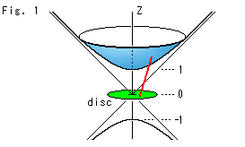
Look at Fig. 1.
The metric ds of Poincare disk in uv-coordinates is, as we saw previously,

The source surface of this metric is the upper half of hyperboloid that we saw in Chapter 5;
The substance of uv-plane that has the character (metric) of a sphere is a sphere. But the hyperboloid is not substance. The uv-plane simply corresponds to the hyperboloid.
Poincare disk is horizontally set at z = 0 on the asymptotic surface (circular cone) of hyperboloid. The hyperboloid actually expands to infinity but, for easy observation, its upper part is cut off. Some people call the hyperboloid Minkowski model.
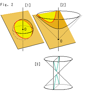
Look at Fig. 2.
[1]: We can get a straight line (geodesic) on a sphere by slicing it with a plane that passes the origin O. The red curve is a circle.
[2]: We can also get a straight line (geodesic) on the hyperboloid by slicing it with a plane that passes the origin O. The red curve is a hyperbola.
The sphere and the hyperboloid have many common points. In the course of time we will see what they are.
[3]: If we cut a cone by a plane like this, we get a hyperbola, too. But do not misunderstand, this hyperbola is completely different matter from the red hyperbola on the hyperboloid.
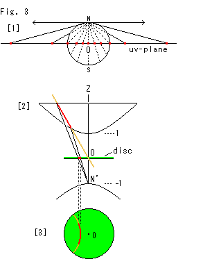
Look at Fig. 3.
[1]: Points on a sphere are projected from its north pole N to the uv-plane that passes the origin O (the center of sphere).
[2]: There is no north pole like [1]. So we make projection from point N' (z = -1) on the lower hyperboloid as shown. We are observing [2] of Fig. 2 in parallel with the brown slicing plane. The red line on the hyperboloid is projected to Poincare disk.
[3]: It is a bird's-eye view of Poincare disk in [2]. The hyperbola on the hyperboloid is now a circular arc on Poincare disk. That is, the hyperbola on hyperboloid is a hyperbolic straight line.
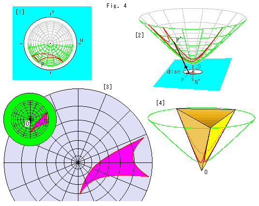
Look at Fig. 4 above.
[1]: A hyperbolic triangle is on Poincare disk.
[2]: The triangle is transferred from [1] by projecting from point N'. Point P corresponds to point P'.
[3]: The small green disk is Poincare's disk with a triangle. The big purple disk is the bird's-eye view of the hyperboloid with the triangle transferred from the green disk. When we carefully compare circular grid of the purple disk with that of the green disk, we find that in the green disk, the farther we go from the center, the narrower the gaps between the concentric circles become. On the contrary in the purple disk, the farther we go from the center, the broader the gaps between the concentric circles become. The actual gaps on the hyperboloid are nearly ![]() times as wide as the bird's-eye view.
times as wide as the bird's-eye view.
[4]: A hyperbolic triangle on the hyperboloid fits in a triangular pyramid exactly.
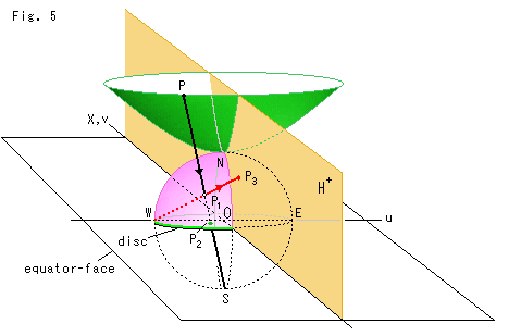
Look at Fig. 5 above.
So far in our study, we have looked at transformations of various models. Now, let's combine four models in one illustration, namely a hyperboloid, hemisphere, Poincare's disk and upper half-plane .
We place Poincare's disk at the origin O and cover it with a hemisphere. The hemisphere is now a hemisphere model. The zenith N of hemisphere touches the bottom of the hyperboloid, and the equator is the circumference of Poincare's disk.
Next we set a half-plane on the equator-face, that vertically cuts the hyperboloid and the semisphere as shown. The half-plane becomes the upper half-plane ![]() . X-axis of the upper half-plane is on top of v-axis of Poincare disk.
. X-axis of the upper half-plane is on top of v-axis of Poincare disk.
As shown by the black arrow line, we project a ray from point P on the hyperboloid. The projected line arrives at the south pole S through the (northern) hemisphere and the equator-face (Poincare's disk). Points ![]() and
and ![]() , through which the projected line passes, correspond to point P.
, through which the projected line passes, correspond to point P.
Next, as shown with the red arrow line, we project a ray from the west end point W (u = -1) through point ![]() on the hemisphere, and we get point
on the hemisphere, and we get point ![]() on the half-plane
on the half-plane ![]() that corresponds to point P.
that corresponds to point P.
Four points P,![]() ,
,![]() and
and ![]() are on the plane that passes point S and W. If we move one of the four points, all other three points move at a time.
are on the plane that passes point S and W. If we move one of the four points, all other three points move at a time.
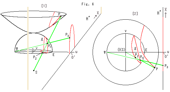
Look at Fig. 6 above.
All red lines are hyperbolic straight lines. They are equal, but each appears differently in shape and size due to a model we use. The figure shows how such straight lines are connected by projection rays. We translated the upper half-plane ![]() along u-axis and set the origin at point O'. It is good for our observation though the origin O' is different from the origin O of other models.
along u-axis and set the origin at point O'. It is good for our observation though the origin O' is different from the origin O of other models.
[1]: The shape of hyperbolic straight line is a hyperbola for the hyperboloid, a vertcal semicircle ![]() for the hemisphere, a circular arc for Poincare disk, and a semicircle for the upper half-plane. The semicircle on the upper half-plane is drawn large by the amount of translatation from point O to point O'. But it does not matter if we use a ruler with wider scale according to the translation.
for the hemisphere, a circular arc for Poincare disk, and a semicircle for the upper half-plane. The semicircle on the upper half-plane is drawn large by the amount of translatation from point O to point O'. But it does not matter if we use a ruler with wider scale according to the translation.
The two green rays intersect at point ![]() . The four points P,
. The four points P,![]() ,
,![]() and
and ![]() are always on a common plane that passes through both points W and S. That is, if one of four point is on the plane, all other three points are on the same plane. This plane is always perpendicular to the equator-face. And if we move one of the four points, all of others move simultaneously.
are always on a common plane that passes through both points W and S. That is, if one of four point is on the plane, all other three points are on the same plane. This plane is always perpendicular to the equator-face. And if we move one of the four points, all of others move simultaneously.
[2]: It is a bird's-eye view of [1] with u-axis set in horizontal. The beeline ![]() is a semicircle on the hemisphere. It is the vertcal cut end of the hemisphere.
is a semicircle on the hemisphere. It is the vertcal cut end of the hemisphere.
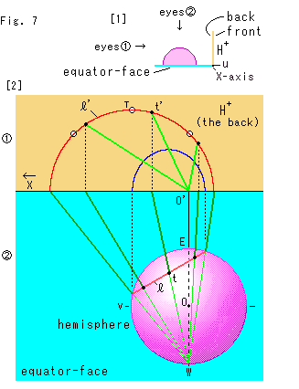
Look at Fig. 7.
An illustration helps our understanding very much. But, in a case, we are carelessly tricked by some illustration. You might think that point ![]() in Fig. 6 should be at the peak of the semicircle on the upper half-plane when point
in Fig. 6 should be at the peak of the semicircle on the upper half-plane when point ![]() is at the peak of the semicircle
is at the peak of the semicircle ![]() on the hemisphere. But actually it is not always true.
on the hemisphere. But actually it is not always true.
[1]: It shows the layout in our site. The pink hemisphere is on the sky blue equator-face, and the yellow upper half-plane ![]() stands at the right. We observe them in the directions of our eyes
stands at the right. We observe them in the directions of our eyes![]() and eyes
and eyes![]() .
.
[2]: The upper ![]() is the upper half-plane in our eyes
is the upper half-plane in our eyes![]() and the
and the ![]() lower is the equator-face with the hemisphere.
lower is the equator-face with the hemisphere.
On the upper half-plane in our eyes![]() :
:
The upper half-plane we see is the reverse side, and the positive direction of its X-axis is leftward. The green lines are projection rays from point W. The red semicircle ![]() is a hyperbolic straight line that corresponds to the red line
is a hyperbolic straight line that corresponds to the red line ![]() (semicircle) on the hemisphere. Three black spots on the red line
(semicircle) on the hemisphere. Three black spots on the red line ![]() correspond to those on the hemisphere, and point t' corresponds to point t. Three marks
correspond to those on the hemisphere, and point t' corresponds to point t. Three marks ![]() indicate the peak T and two points located at 45
indicate the peak T and two points located at 45![]() from point T. The blue curve is the image of the red line
from point T. The blue curve is the image of the red line ![]() formed by parallel projection. It is not a semicircle but semi-ellipse.
formed by parallel projection. It is not a semicircle but semi-ellipse.
On the hemisphere in our eyes![]() :
:
The red line ![]() is a hyperbolic straight line that is a vertical semicircle on the equator-face. Three black spots on the red line are point t at the peak and two points located at 45
is a hyperbolic straight line that is a vertical semicircle on the equator-face. Three black spots on the red line are point t at the peak and two points located at 45![]() from point t. Projection rays from point W pass through the hemispher inside to outsite at the red line
from point t. Projection rays from point W pass through the hemispher inside to outsite at the red line ![]() , which is shown in color contrast.
, which is shown in color contrast.
Projection transfers a semicircle to a semicircle, but not peak to peak. The peak point t of the semicircle ![]() does not correspond to the peak point T of the semicircle
does not correspond to the peak point T of the semicircle ![]() but to point t'. It exceptionally happens that three marks
but to point t'. It exceptionally happens that three marks ![]() and three black spots meet each other when both surfaces of the semicircle
and three black spots meet each other when both surfaces of the semicircle ![]() and the upper half-plane are in parallel, when the four points P,
and the upper half-plane are in parallel, when the four points P,![]() ,
,![]() ,
,![]() are on the plane that vertically passes u-axis.
are on the plane that vertically passes u-axis.
It is no problem for us if we pay attention to only a visually particular point, a vertex of a triangle for example. But we must be careful when we observe a point on a smooth curve or surface.
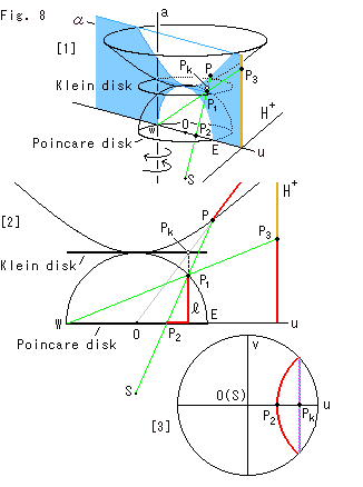
Look at Fig. 8.
Now we draw all the five models, including Klein disk, in a single diagram by using three projection rays.
[1]: We take a look at only points and omit figures. Point ![]() is on Klein's disk. Five corresponding points P,
is on Klein's disk. Five corresponding points P, ![]() ,
, ![]() ,
, ![]() and
and ![]() are on the plane
are on the plane ![]() . Every point corresponds to others. Plane
. Every point corresponds to others. Plane ![]() rotates when corresponding points move. The axis of the rotation is the straight line a that stands up passing point W. Plane
rotates when corresponding points move. The axis of the rotation is the straight line a that stands up passing point W. Plane ![]() is exactly on u-axis now.
is exactly on u-axis now.
[2]: Plane ![]() is faced to us and the upper half-plane is parallel with our eyes. Now we get an easy picture to see. Every red line is a hyperbolic straight line but none looks curved. The gray line that goes upper right from the origin is a projection ray that pierces Klein disk. This line also shows a cross-section of the plane that cuts the hiperboploid through the origin O. The line of intersecton of this plane and the hiperboploid is the red line that passes point point P. The point
is faced to us and the upper half-plane is parallel with our eyes. Now we get an easy picture to see. Every red line is a hyperbolic straight line but none looks curved. The gray line that goes upper right from the origin is a projection ray that pierces Klein disk. This line also shows a cross-section of the plane that cuts the hiperboploid through the origin O. The line of intersecton of this plane and the hiperboploid is the red line that passes point point P. The point ![]() at which ray OP pierces Klein disk corresponds to point P and just under point
at which ray OP pierces Klein disk corresponds to point P and just under point ![]() is point
is point ![]() . That is say, if we ray from point
. That is say, if we ray from point ![]() straightly onto the hemisphere, where we get point
straightly onto the hemisphere, where we get point ![]() .
.
The diagram changes a little when plane ![]() is not on u-axis. But the rlations among corresponding points do not change.
is not on u-axis. But the rlations among corresponding points do not change.
[3]: Klein disk is lying on top of Poincare disk if we look down them in parallel with Z-axis. The violet chord that passes point ![]() is a hyperbolic straight line on Klein disk and the red circular arc is that of poincare disk.
is a hyperbolic straight line on Klein disk and the red circular arc is that of poincare disk.
Now we can join all the five models, and we can travel one model to the other though we may have to change a ray at ![]() or
or ![]() .
.
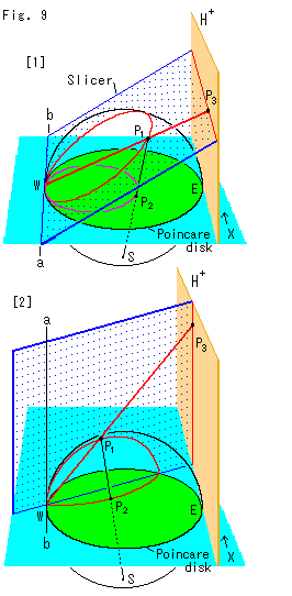
Look at Fig. 9.
We have used the plane named Sliser that cuts the semisphere. Let us see two peculiarities on the upper half-plane with Slicer. They are visual straight lines. One is horizontal and the other is vertical.
[1]: The hinge line ab contacts the hemisphere at pointW (u = -1). The upper half-plane is parallel with the hinge line ab. And Slicer cuts the hemisphere and makes a circular cut end, and simultaneously cuts the upper half-plane in horizontal. By the red ray from point W, point ![]() horizontally moves when point
horizontally moves when point ![]() moves along the circular cut end. Also by the black ray from the south pole S, point
moves along the circular cut end. Also by the black ray from the south pole S, point ![]() on Poincare disk draws a circle. In this case both circles on the sphere and Poincare disk look passing point W.
on Poincare disk draws a circle. In this case both circles on the sphere and Poincare disk look passing point W.
The horizontal line on the upper half-plane is not a semicircle with its center on X-axis so that it is not an ordinary hyperbolic straight line. But it can be regarded as a circle with infinite radius. On the other hand, all ends of hyperbolic straight lines on the hemisphere and Poincare disk seem to joint at point W, and each forms a loop. So then it seems that the horizontal line on the upper half-plane must form a loop somewhere like point W.
[2]: We stand up Slicer with its hinge line ab that vertically passes point W. This Slicer is the same as plane ![]() in Fig. 8. Slicer cuts the hemisphere and makes a semicirclar cut end, and cuts the upper half-plane in vertical. And point
in Fig. 8. Slicer cuts the hemisphere and makes a semicirclar cut end, and cuts the upper half-plane in vertical. And point ![]() vertically moves when point
vertically moves when point ![]() moves along the semicircular cut end. Point
moves along the semicircular cut end. Point ![]() draws a circular arc on Poincare disk. (In case of Klein's disk, a hyperbolic straight line is the line of intersection of Slicer and the disk.) Then it seems that the semicircle on the hemisphere passes point W and that of Poincare disk as well. It agrees with the half-line on the upper half-plane.
draws a circular arc on Poincare disk. (In case of Klein's disk, a hyperbolic straight line is the line of intersection of Slicer and the disk.) Then it seems that the semicircle on the hemisphere passes point W and that of Poincare disk as well. It agrees with the half-line on the upper half-plane.
Let a hyperbolic straight line on the hemisphere or Poincare disk be A, and let a hyperbolic straight line that corresponds A be B. Conditions are;
B is a horizontal straight line if both ends of A look passing point W.
B is a vertical straight line if only one end of A looks passing point W.
Then what will hapen when point ![]() gets close to point W ? It can be melted if we recall that all models is open. Neither point
gets close to point W ? It can be melted if we recall that all models is open. Neither point ![]() nor point
nor point ![]() is able to arrive at point W. Point
is able to arrive at point W. Point ![]() never get to X-axis. Therefore the red ray W-
never get to X-axis. Therefore the red ray W-![]() -
-![]() never be exactly in vertical or horizontal though it can unlimitedly get to be so.
never be exactly in vertical or horizontal though it can unlimitedly get to be so.
As to Klein disk, the movement of point ![]() and point
and point ![]() is the same as that of Poincare disk. All we have to do is to know that a circle and a cicular arc on Poincare disk correspond to an ellipse and a straight line respectively.
is the same as that of Poincare disk. All we have to do is to know that a circle and a cicular arc on Poincare disk correspond to an ellipse and a straight line respectively.
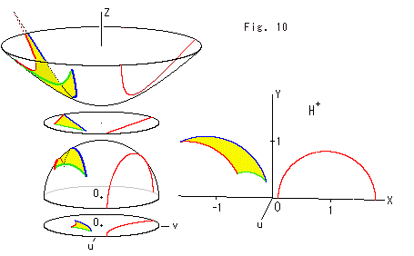
Look at Fig. 10.
A triangle and a straight line are drawn every mode. All triangles are congruent. All straight lines are located at the same hyperbolic position. Each model is separated from an adjacent model for easy to see but Z-axis is common for them except the upper half-plane ![]() . The upper half-plane was located at the origin O. Its front side faces us so that the direction of u-axis is to us.
. The upper half-plane was located at the origin O. Its front side faces us so that the direction of u-axis is to us.
Now we can freely image to transfer from one model to the other.